


Building Energy Modeling and Simulation
This paper discusses two types of building modeling tools used for planning individual buildings and neighborhoods based on various parameters such as proper orientation, massing, solar access, shade and shadow analysis, wind direction, and thermal comfort. First part of the paper discusses an older modeling technique used to provide solar access[1] to the existing and new buildings at an individual, community and citywide scale. And the second part of the paper focuses on a modern-day modeling software that includes the features of the older modeling tool and in addition to that offers a wide range of services to aid decision-making process right from the concept design to finalized building design.
First modeling tool described is “Solar Envelope” – a method of creating a balance between population density and solar access. This was developed and refined by Ralph Knowles, professor at the University of Southern California’s School of Architecture and author of three fascinating books on this topic. Solar Envelope can be defined as a set of imaginary boundaries, enclosing a building site, that regulates development in relation to the sun’s relative motion. The concept of solar envelope was developed in the 1980s. Solar envelope is conditioned in space and time; it assures solar access to the properties surrounding a given site. Solar envelope accomplishes this by limiting the size of on-site buildings, thus avoiding undesirable shadows above a boundary along neighboring property lines. According to Knowles, the buildings designed within this boundary will not overshadow their surroundings during critical times of the day and year. His research shows that, if generally applied as an instrument of zoning, the solar envelope will not only allow potential growth but will open new aesthetic possibilities for architecture and urban design. [1][2]
In the past, buildings were designed to adapt to the local climate through a consideration of their location, orientation and shape, and appropriate building materials. This resulted in many vernacular building styles in different parts of the world. In contrast, most modern buildings look the same wherever they stand. They are made from the same materials, they follow forms that are driven by fashion rather than by climate, and are most often randomly located and oriented, indifferent to the path of the sun and the prevailing wind conditions. [1]
In an urban environment, building orientation is generally determined by street layout, and one building can easily overshadow another. High-rise buildings further complicate solar access. Solar envelope can design individual buildings or as a single envelope for a group of houses, a neighborhood, a district or even an entire city. When the solar envelope is applied in line with existing buildings, new construction will always be shaped and proportioned with reference to the older ones. Solar envelope allows architects to design according to sunlight without fear that their ideas will be cancelled out by future buildings. Solar envelope also recognizes the need for development and high population densities and so it defines the largest container of space that would not cast shadows off-site at specified times of the day. [2]
Geometry of the solar envelope
Solar access to an individual building is determined by four factors: latitude, slope, building shape and orientation. But solar access to a city is determined by seven factors, the previous four plus the height of the buildings, the width of the streets, and the orientation of the streets. Solar envelope is not only defined by the path of the sun, but also by fixed parameters set by the designer. Choosing these will determine the balance between solar access and development potential. The limits for the solar envelope derive their vertical dimensions from the sun’s daily and seasonal movements. Thus, unlike other massing tools, solar envelope can develop both vertical and sloping spaces. As a result, the buildings and city blocks that fill these imaginary solar envelopes are more likely to have unique shapes. [2]
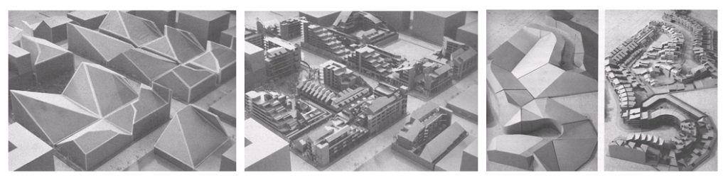
Above figures show projects with solar envelopes on grid-iron and curving streets. [1]
Despite being an innovative and easy-to-use tool, solar envelope falls short when it comes to designing contemporary buildings, which require consideration of parameters other than just solar access. Hence, the second part of the paper focuses on a modern-day tool – “Autodesk’s Ecotect Analysis” that includes solar envelope’s features and provides additional analyses such as shadow and reflection, wind direction, thermal comfort, carbon emission, and cost analysis to help users in creating sustainable designs.
Introduction to Ecotect
Ecotect Analysis is a comprehensive Autodesk software offering concept-to-detail sustainable design and analysis tool. It provides a wide range of simulation and analysis functionality to improve performance of new and existing buildings. Ecotect is an innovative building analysis software package featuring a user-friendly 3D modeling interface fully integrated with solar, thermal, lighting, acoustic, and cost functions. Ecotect Analysis is primarily used by students and professionals in architecture and environmental engineering field to evaluate a building’s performance through simulation and powerful 3-dimension feedback to explore environmental factors such as sun path, daylight, ventilation; etc. [3]
Ecotect[3] can calculate and visualize solar radiation on building surfaces throughout the year at a neighborhood scale as well as simulate sun penetration into individual rooms to help with shading design. Ecotect is flexible and suitable for early-stage designs. Users can build 3D models directly in the software and export it to more detailed modeling tools. [3]
Ecotect Analysis was created by Dr. Andrew Marsh of Square One Research Centre in Cardiff University, Wales, United Kingdom. In June 2008, Ecotect was acquired by Autodesk to add to an array of tools that can augment the Revit BIM environment. From March 20th, 2015, Autodesk incorporated some of the Ecotect Analysis functionalities into Revit product family to offer a comprehensive sustainable analysis experience. This change allowed Autodesk to shift resources, maximize development efforts on BIM and cloud-based solutions for building performance analysis and visualization. Users with Autodesk Ecotect product license have access to other web-based software such as Autodesk Green Studio, DOE OpenStudio to evaluate alternative energy efficiency techniques and carbon neutrality. [4]
Key Features of Ecotect Analysis
Ecotect performs five key functions – modeling and visualization, central repository for all building data, analysis functions, import and export capabilities and working with other validation tools such as EnergyPlus, Radiance, and OpenStudio. [9] Ecotect manages wide range of tasks from solar analysis, sun and shadow studies, daylighting and lighting, thermal performance, whole building energy analysis, to weather normalization. The interactive sun path tool in Ecotect allows the user to study the impact of natural light and shadows on the exteriors and interiors of the project for any location. Ecotect can create solar studies for any moment in time, and for any specified time range. The heating and cooling load design feature in Ecotect is based on ASHRAE Handbook of Fundamentals. Ecotect can calculate the thermal loads by taking into account internal loads, solar gain, and the effect of the building envelope. It can analyze the effects of occupancy, infiltration, and equipment. [5] Ecotect offers an interactive approach to select different surface materials and compare the resulting changes to internal lighting levels, reverberation times, hourly and monthly heat loads at different times of the year. It allows the user to add new openings at any time to see their effect on daylighting, thermal response, and overall building costs. [5]
Conceptual and schematic design phase is the perfect time for deciding the building form, environmental factors, and the choice of materials. Ecotect can study the future thermal performance of the building and suggest relevant adaptations in order to maintain occupant comfort. Designers can use Ecotect to generate vital design information even before the building form has been considered. Ecotect can incorporate detailed climatic analysis, confirm longitude and latitude and time zones to evaluate the impact of solar radiation, available sunlight, and prevailing winds. [5] Ecotect can be used to locate and orient the project site and calibrate weather impact on the building. It can provide 3D stereographic sun paths on the model and calculate overshadowing from adjacent properties. Ecotect can analyze wind direction, wind speed, air temperature, and relative humidity. [6] Ecotect offers comparative analysis of simple sketch models to aid the decision-making process from the beginning. Ecotect targets the earliest stages of design, a time when simple decisions can have far-reaching effects on the final project. For maximum benefit, Ecotect should be used during a project’s concept design phase and as the project is finalized, it should be exported to more focused validation tools such as EnergyPlus, Radiance, and OpenStudio to calculate accurate savings. [7]
Modeling a Building in Ecotect
Building energy analysis requires spatial information which is essentially a simulation of energy moving in and out, through the rooms and volumes within a building. In the past, this information was manually calculated from 2D drawings. Today, all this information is available in a Revit model which is much easier to interpret than other 2D drawings. These 2D drawings can be exported to Ecotect to speed up the simulation process. Ecotect can be applied at the beginning of a design process and can be repeated innumerable times during different phases of a project when change is still possible. [6]
For creating a thermal model, Ecotect offers a set of specific guidelines –
- Use single planes to create rooms and zones irrespective of the material thickness.
- Each room or zone with adjacent rooms should have an overlapping surface for thermal calculation.
- Ecotect only cares about floors, windows, voids, and partition elements as they have very specific roles in a thermal analysis.
- External shading systems should be created as a separate thermal zone.
- Objects outside thermal zones or overlapping non-thermal zones are considered as underground or adiabatic surfaces.
Creating a thermal model in Ecotect requires all building elements to belong to a zone, so it is relatively simple to count the number of floors, walls, and windows within each zone. Using zones, Ecotect can automatically calculate which zones are adjacent to each other as well as the exact surfaces through which inter-zonal heat exchange takes place. Each zone can define their own set of internal conditions such as occupants, lighting, equipment loads, and thermostat set points. [8]
Ecotect does not impose a limit on the number of zones created, but if the model is exported to other tools such as EnergyPlus or Radiance, there might be a limit on the number of zones. Hence, the user is expected to know the variations within each tool. Also, more zones will take longer time for calculation and create more data to deal with.
As the complexity of a model increases, it can be exported to a range of application-specific tools for more detailed analysis. Ecotect supports a wide variety of formats such as Radiance, a radiation-based lighting simulation package from Lawrence Berkley Laboratories, VRML for interactive 3D visualization, the DOE-2 and EnergyPlus thermal simulation tools from the US Department of Energy and a range of freeware ray-tracing rendering tools. [9]
Computer-Based Sketching Experience in Ecotect
Ecotect can produce simple and quick hand sketch models that can be used for both general and detailed analysis. For this functionality, Ecotect had to move away from the traditional CAD-like environment that focuses on drafting rather than modeling. Ecotect can store geometry from one element and apply it in the future. It can recognize change in the parent element and reduce data entry time by making subsequent changes for all the elements related to the parent element. [10]
Visual Feedback within Ecotect
Architectural design process is visual in nature, especially during the early stages where the building form is still being established. Ecotect can show solar and lighting calculations in visual formats. However, there are a majority of calculations that are not inherently visual, but there are ways to make them more so. For example, when using ray-tracing techniques, Ecotect can display each ray as it is generated and provide an indication of how the calculation is progressing. This allows the user to identify anomalies in the display. Such techniques can be implemented for surface area, volume, daylighting, and acoustic calculations. [10]
Calculations within Ecotect
In Ecotect, all calculations are based on basic assumptions and default values set by the user which can be changed at any time. Inexperienced users or those requiring a quick result, need to fill only a certain level of information. As the design is gradually resolved, more detailed information can be added to the model, making the results more accurate. In Ecotect, ground temperatures are automatically calculated by dropping 10 graduated depth bands 7 feet below ground to interpolate between hourly and annual average ground temperature. [10]
Miscellaneous Settings within Ecotect
In addition to creating thermal zones, Ecotect requires type of heating, ventilation, and air-conditioning (HVAC) system used within the space. These systems can be chosen at a conceptual level for calculating comfort and space loads. Ecotect also allows the user to enter a coefficient of performance (COP) for any system to estimate overall energy requirements. Ecotect aims at generating most efficient building design with lowest possible space loads by applying passive techniques. It also allows the engineer to choose most efficient and appropriate mechanical systems to meet any outstanding loads that cannot be met by passive means. [8]
Ecotect Strengths & Weaknesses
Ecotect is capable of importing complex geometries from CAD and other 2D formats and offers some modeling tricks to simplify them to a certain degree. Users have found Ecotect fast and easy-to-use. The simple and intuitive interface of Ecotect has proved beneficial for the students to evaluate their designs. With appropriate integration into courses, students can understand concepts of simulation as a whole. But if they become too reliant on Ecotect, they can fail to develop their own intuitive judgement of the environmental conditions within their building. Hence, it is important for the users to understand the principles behind Ecotect’s calculations so that they can make estimates and detect where errors might be occurring. [10]
Conclusion
Modeling and simulation tools are different from rating systems and best practices; instead of offering strategies, modeling tools predict energy consumption of proposed designs and allow the users to make adjustments until a satisfactory energy profile is reached. They inform designers about the project’s performance against the rating systems, provide instant feedback on decisions, and consider trade-offs between design elements. [11] Tools like Ecotect offer simple and appropriate mechanism for assisting both inexperienced and advanced users for modeling and evaluating sustainable designs.