


The oil and gas industry faces significant challenges, especially during the design and construction phase of oil refiners where it considered that oil storage facilities and the safe distance between tanks have the largest share of these challenges due to frequent accidents. This study developed based on previous research and a review of the literature on this field. The best criteria, recommendations and strategies have been used to of NFPA and API standards to prove the quality of this research.
The aims are to determine the safe distance between tanks and to develop trust in simulation software by using the CFD analysis. Moreover, the study looked to other factors which lead to frequent accidents such as a type of material used to build the tanks, barriers and fire protection facilities. The simulation software in the past was not too accurate on the results, but as technology advanced, this software became more sophisticated. Also, most of the previous researches relied on theoretical data or experiments.
However, after I conducted the CFD analysis simulation, it proved that the minimum safe distance between tanks was found to be 15 m in which the wind had minimum friction on the walls of tanks and fire will have less impact on near tanks. For analysis, a group of tanks taken into consideration in which four tanks were present. The study conducted for aboveground tanks with a fixed or floating roof only. Where it proved that the stainless steel was the best material for tanks as it can bear very high temperature and less likely of ignition.
Chapter 1: Introduction
The oil storage stations are considered to be one of the essential facilities in oil refineries and petrochemical plants where there are many standards and techniques used to design the oil storage tanks which has contributed to the development of other systems such as determining the safe separation distance between the tanks and the fire protection system.
Over the last decade, the storage tanks have not received enough attention from construction companies or owners, where it has become dangerous to employees, individuals, society and the environment — also, has left a lot of serious harm to the economy and profits.
1.1. Background
According to the ( study of storage tank accidents) conducted by James I. Changa,*, Cheng-Chung Linb; that during the period between 1990 and 1999 North America recorded the highest numbers of oil tanks accident, with an average of 36 accidents compared to the average in South America and Africa by two accidents each. However, the Oil storage tanks farm usually are less interested from the owner due to lack of accidents and the development of modern technologies.
In case of a fire accident in the oil storage tanks field, it is likely neighbouring tanks will be affected, where the effects of heat caused by fire are very high. This will lead to a consequent impact on the stock of the tanks. The heat caused by the fire will also contribute to the high temperature of the vapour, gases and liquid, which will result in significant increases in the tank the vapour space pressure. This will lead to a serious situation by exceeding the vapour through (Pressure Vacuum Relief Valves. PVRV) which will allow the vapour leakage and rises into the atmosphere and ignite. Adding to that, if the neighbouring tanks have flammable liquid, it will be likely to ignite the vapour and caused a fire. To avoid series hazards, there is an essential need to reassess the space distance between storage tanks and find the best ways to avoid any future fire or disasters.
The current design standards are extensive, and it has proved useful but are not enough to reduce the risks. This because of the way that the current design standards in identifying the safe space distance between the oil tanks and protection systems according to experience and understanding instead of appropriate designing. Based on that, this dissertation will elaborate numerous modules, scenarios and mathematical concepts that can help further research on the safe separation distance between the oil storage tanks and predictability of fire before igniting. Moreover, it will include the heat motion, temperature, radiation distribution and the interaction with neighbouring storage tanks contents.
1.2 Aim of Project
This study aiming and investigate one of the challenges which the oil and gas industry. Many types of research submitted on this field according to international standards and a lot of experiments were conducted. My target on this study is to determine the safe distance between tanks and to develop trust in simulation software by using the CFD analysis. Additionally, some factors were addressed, such as a type of material used to build the tanks, barriers and fire protection facilities. The CFD analysis simulation will be used to prove the investigation and measurement of the other factors such as the pressure, wind direction and flame movement. The work based on four oil tanks, and we will use one of them to apply the scenarios to ensure the best results.
1.3 Research scope
In this project, CFD analysis was done of the fuel tanks in order to find the minimum safe distance between the tanks. The main purpose of doing CFD analysis studies the fire impact on nearby tanks. The research will address the wind behaviour, fire flame movement, the airflow and the heat flux between the oil storage tanks. This project does not involve any experiment because the idea of this project was to present a solution for experimental setups. The software now is so accurate that they provide 95% of correct results, which can be increased by using different types of mesh. No calculation was involved; it was simulation-based research to provide the minimum safe distance between the tanks.
Chapter 2: Literature review
2.1 Introduction
Safety is a top priority in the oil and gas industry. Its importance is recognised all over the world, in particular, due to repeated major accidents in the oil and gas field — the process of dealing with hazardous materials in the oil and gas industry classified as extremely important. So, most of the owners are doing their best to raise public awareness and work to increase responsibility and reduce disaster costs. The manufacture, handling and use of hazardous materials significant risks not only to workers but also to the public, property and the environment. At the beginning of the oil and gas industry, there were many fire accidents on the oil storage tanks in widespread in various parts of the world. But the passage of the time and the improvements of the design, construction stage, fire protection system and proper implementation of the safety standards. As a result, the recorded fire incident have decreased dramatically due to massive development and interest in this field. Our memory goes back to the massive fire that occurred in 2005 in the United Kingdom at (Hertfordshire Oil Storage Terminal).
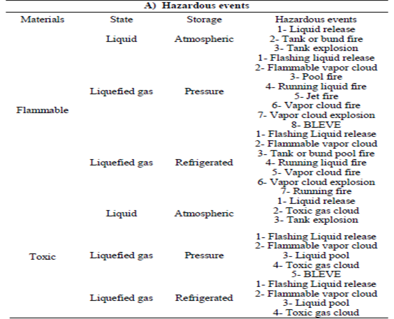
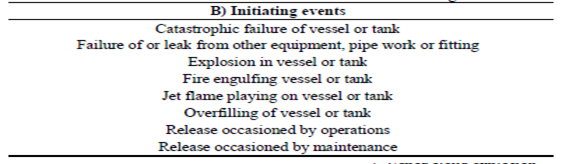
Table 1 Hazardous Event
2.2 Previous Research
By numerical CFD simulation software, the accidents and leaks in the tank can analysed. Moreover, it can be used for proper safety planning and analysis to avoid the consequences of accidents in oil storage tanks. For instance; according to study research by (Liu et al., 2017) that in China, the analyses were carried out to investigate the oil spill process and the main overflow factors. The results showed that the quality of the CFD simulation work better than SPLOT. However, the number of failures between two system results about nearly 5% for the simulation software, which means the CFD simulation is more accurate.
There are many studies carried out on Fire physics and most of the fire research associated with hydrocarbon fires where it proved that the size of thermal radiation and flame surface are the most important factors that influence the properties. As an example, thermal radiation studies have contributed to determining the temperature, flow rate, effects and the consequences on that. Therefore, it is important to know the size of the thermal radiation and impact on other tanks surface. According to (Ufuah and Bailey, 2011) It has found that the importance of heat radiation extends the means to determine satisfactory distances between radiation sources and targets.
Tank farm fires are high risk because they can lead to socioeconomic losses, injuries, fatalities and serious environmental consequences. As mentioned above, the spread of tank fires depends on characteristics, prediction, of thermal radiation and heat transfer, which depends on the response of the surrounding factors such as fuel type. Other factors affecting the thermal stability of the oil reservoirs are the safety of the structure, taking into account the type of material, type of fuel, separation distastes between the tanks. Based on (Pantousa, 2018) research; the intrinsic fire resistance of thin-walled tanks and to predict their failure by investigating that. Where tested the heat flow rate and transfer between the tanks processed by thermomechanical analysis.
During the design stage, most of the fire consulting companies using NFPA standard to be designing a fire protection system and measuring the safe distance between fuel tanks by known heat release rate, identify the fuel element and measuring the centre’s distance of between adjacent fuel tanks.
In general, the oil and gas industry can create dangerous conditions by causing fires, explosions, explosive chemical sounds, electric shocks, etc. These lead to damage to health, environmental damage and loss of efficiency. These risks may be due to the presence of cleaning chemicals, hazardous gases, incorrect closure labels, vapours, fumes, dust, heat or excessive cold. Campfires in the atmosphere are very common in industrial plants. Recently, there were several storage tanks in industrial plants in Asia. The bow tie diagram describes the causes and factors responsible for the different types of fires in storage tanks. According to many studies on this field; that nearly 70% of the fire accidents took place in gas stations or refineries, while fires and explosions caused 90% of these accidents.
Moreover, there are accidents caused by natural factors such as lightning strikes or caused by human factors, malfunctions, lack of maintenance, sabotage, cracks, leaks and breaks in cables. Most of these accidents could have been avoided if adequate safety management programs had been put in place and good engineering practices had been implemented (Ibrahim and J Rao, 2017)
2.3 Benefits of CFD simulation and New Results
Over the last century, the research on this topic was theoretical and practical, but nowadays, most of the owner and consulting companies are using CFD simulation to analyse the resources and results to develop research and criteria on this field. The CFD simulation used to give accurate results and satisfactory as it demonstrates the usefulness of practical work and modern technology. It also helps to provide accurate calculations for the safety margin between the tanks and the type of tanks most suitable for fuel should be. The main problem with the previous results was that the researchers had to do a lot of calculations to show the safe distance between the tanks, but with CFD software, the calculations could easily be demonstrated.
Practical work requires a lot of capital to prove the point, and the experiment also requires plenty of room for performance and special equipment, While when using CFD simulation, the results could be easily demonstrated. Because today, the software delivers up to 95% of the correct results. Therefore, it can be said that the research done with the CFD software is more accurate and more accurate than the practical work since many errors can modify the results of an experiment, even if reviewed.
Chapter 3: Review of Standard Documents
3.1 The benefits of the design stage.
The storage tank farms usually are having equal heights, size, and diameter even though they might be of different varying capacities in the way of performing. Adds the appropriate design of the tanks during the design stage, many values and economic benefit to the owner where it helps to develop appropriate plans by the fire service department to avoid the fire hazards in future. From the industrial side, the distance of the desirable tank depends on fuel type to be stored in the tanks. The oil tanks are generally constructed from steel and some cases from polyethene. Furthermore, some tanks are either having floating or fixed roofs.
The are many institutions, agencies and authorities have standards which can be applied on layouts of tanks farm during engineering stages such as the American Petroleum Institute (API) and National Fire Protection Association (NFPA). The values of tank farms are providing buffer spaces between tanks farm and public services for environmental reasons. Furthermore, it always should be taken into consideration that the distance between the tanks on the layout should be easy access to ensure the maximum safety potential.
There are many requirements for the oil tanks farm:
- The existence of sufficient separation distance between oil tanks as per the standards.
- Provide a proper fire protection system along with the emergency response plan.
- In case of oil leakage from the oil tank, it can be established an emergency environmental plan to containment the leakage and separate the operation of the tank from the process areas.
- The dams must design to face the strength of huge pressure that could be generated by an oil spill and the storage capacity of the spilt fluid.
There are many criteria and models to determine the safe separation distance between oil tanks. There are several mathematical systems used, such as Mudan’s method, Shokrie Beyler’s method and Point source model. The way to achieve that is to calculate thermal radiation and heat flow rate at different distances between a burning tank and the adjacent tank target tank.
3.2 Specifications of the oil storage tanks
There are many standards such as National Fire Protection Association “NFPA 30” and American Petroleum Institute “API 650”, that classified the designs of hydrocarbon storage tanks based on several ratings such roof design and pressure. According to NFPA 30 Standard, the storage tanks can be identified as that the capacity for aboveground outdoor combustible liquid shall not exceed 30,000 gallons, where is in for aboveground indoor flammable liquid shall not exceed 20,000 gallons.
The oil storage tanks usually build from steel, unlike the underground storage tanks which build from fibreglass and concrete. The difference remains in design way either horizontally or vertically. Furthermore, some storage tanks installed by spill collection basin. Besides, some of the storage tanks designed with roof floating and some of them with a fixed roof. According to API650 standard, The material specifications should be certified as per the minimum requirements and should be fitted with high-quality designs specifications with top considerations on the safety side.
3.3 Location and layout of the oil storage tanks
The fire safety system has direct impacts on flammable liquid storage tanks facilities, where the orderly arrangement of storage tanks farm sequentially protects the rest of tanks from spreading the fire. However, there are other facilities can be affected such as plant area, properties and environment if placed next to the flammable liquid storage tanks due to spreading of the fire. Determining the minimum distance between the storage tanks have multiple benefits, where is if the separation distance increases, the hazards will be reduced.
Many standards define specifications and requirements for storage tanks facilities, for instance: (National Fire Protection Association “NFPA 30” and The Health and Safety Executive guidance “HSG 176”).
The main purposes to specify and provide recommendations for space distance between storage tanks are two:
- Prevent other tanks from fire spreading between them.
- Guarantee the proper access for fire service team, as well as ensure the means of escape
Usually, the fire travels between the storage tanks through the flame, which is unlikely or radiant heat, which is one of the most important means of heat transfer to neighbouring storage tanks.
According to LAST FIRE Incident Investigation (2012), The radiated heat radiation caused during the first hours of a surface fire depending on the contents of the tank and the boiling point. It also, shows that radiant heat transfer from tank to other is an important factor in increasing the radiant heat for other tanks. The same study recommends; that the distance between the tanks should be increased by more than one diameter if the radiation of radiant heat to the roof is to be significantly reduced.
The risk will increase in storage tanks farm in case of fire spread to other tanks, especially if some of these tanks contain hydrocarbon products. So, the kinds of tanks should be split on to separate bunds for more precaution and avoid leakage hazards. Among the facilities required in the storage tanks, farm area is fire equipment, such as fire hydrants, pumps, manifolds and strainers, where this equipment should be located within the area. However, the best place for them is to install on the bunds wall but from outside the bund, where it is protected from fire hazards.
As per NFPA Standard, they classified the hydrocarbon liquids storage tanks and arranged them based on classes such as class 1, Class 2, and Class 3. The better arrangement for the most hazardous and it should be close to fire equipment. The firefighting and emergency team needs easy access during maintenance or operation in case of an emergency or fire. Moreover, the storage tanks area should be designed to have enough spaces and accommodate the passage of fire trucks and ambulances.
3.4 Fire accidents in the oil storage tanks
The fire accidents in oil and gas storage tanks pose a load to the owners, and they are concerned about that because those tanks are highly hazardous and contain flammable liquids can ignite any time. This concern is seen as one aspect of the industrial safety issues, and that can have high consequences catastrophic, impacts on the life cycle, environment and economy.
3.5 Heat effect on the oil storage tanks
As known, there are three ways of heat transfer on storage tanks fires and these methods either by radiation or conduction or convection. Beyler (2002) found that thermal radiation is responsible for significant losses in the petrochemical industry due to hydrocarbon fires. Where objects that are far from the fire are heated by direct ignition without contact with flame. Therefore, the radiant heat flux causes the flame to propagate from one object to another.
The radiant heat has a direct impact on storage tanks cantina flammable liquid or hydrocarbon materials, where the heat flux was falling directly, and it is declining with the surface of the tank. To evaluate the radiant heat flux and impacts on other tanks, it should consider many points such as:
- Evaluate the possibility igniting to nearby tanks.
- Evaluate the damage to assets and properties.
- Evaluate the safe space distance between the tanks.
- Evaluate the protection system on the tanks.
The fuel type in the tanks is one of the causes for an increase of radiation heat, where the temperature in some surface requires a high temperature to ignite the vapours or the flammable liquid.
Chapter 4: Theoretical Approach
4.1 Separation Distance between Storage Tanks
In this study, measurable models used to determine the safe space separation distances between The oil storage tanks. These calculations assist in giving figures and coordinates close to the requirements of international standards. Care is taken to calculate the time required for flammability, the amount of radiant heat received, and the amount of steam.
The models showed that the thermal radiant decreased significantly if there is enough and safe distance between the two points of the target point and the source point which will result in a reduction of the vapour pressure in the region.
According to IP Fire protection codes, they established the separation distances between oil storage tanks as per different criteria. The minimum separation distastes between the tanks should have an equal diameter or smaller and all the safe distance should be between 10m to 15 m.
4.2 Emergency response access consideration using the safe distance.
Planning to measure the space separation distance between storage tanks is necessary but should be considered about the proper means of escape and easy access to the emergency response team between the tanks and other facilities. If this case unable to meet due to the operational purpose, then, they must provide a fixed firefighting system. The access to the oil storage tanks which containing hydrocarbons or combustible material must be completely free from any obstacles to facilitate the passage of fire trucks in case of emergency and must have a sufficient fire protection system around that such as fire extinguisher. (TRCI Inventory (2009).
- Application of models
The location of the storage tanks should be carefully selected so that they are away from the properties and individuals, with taking care and caution from spreading the fire to other places. However, it is improbable that the space separation distance standards are entirely safe, but at least it can help to provide enough time for safe evacuation in case of an emergency. According to the Safe Practices Code of the Institute of Petroleum (1981), the oil storage tanks must be accessible to firefighting service.
Chapter 5: NFPA Codes and Application
5.1 NFPA 30 Standards
It is often that the large storage tanks a significant cause of the spread of fires to other storage tanks or locations. It is essential to determine the distance between the tanks of storage, in order to reduce the fire accidents, spread opportunities. Engineering design should be based on the measurement of separation distances to the minimum spacing of the tanks and contribute to the examination of the level radiant heat flow from the burning tank to the others. NFPA 30 is considered one of the best examples in this field to meet the standards required, especially in refineries and petrochemical plants. Therefore, most of the codes which have been evaluated by their experts and their recommendations were adopted that the spacing on fixed roof tanks diameter should be 0.5D and between 5 to10m diameters, whereas the floating roof tanks should be 0.3D. However, some Petroleum companies proposed to increase the space separation distance between the storage tanks, which maybe can be costly for them due to high land value recommended for it. Furthermore, this increase is not the proper solution to minimise the hazards enough to justify expenses. An example of that, NFPA 30 require measuring the space distance for fixed roof tanks over 45m diameter which is nearly 0.66D, where for the floating roof tanks is 0.5D. On the other hand, for less than 45m diameter than NFPA 30 specifications are little.
5.2. NFPA 30 recommendations and strategies.
- The minimum distance for all floating roof tanks with a diameter of less than 45 m is one sixth of the total tank in the vicinity. While for more than 45 m diameter, the sixth is the same.
- The minimum distance for all tanks with floating roofs less than 45 m in diameter is one-sixth of the total tank in the vicinity. While for more than 45m in diameter is a quarter in total.
- The minimum distance for all fixed roof tanks with a diameter of more than 45 m corresponds to one third of the total tanks in the vicinity.
European standers for the minimum safe separation distance have been classification into three classes and based on flash point temperatures. The first class I is where the flash point is less than 21 C for the liquid and class II the flash point for the liquid is between 21C to 55C. Lastly, the Class III is higher than other where the temperature is between 55C to 100C which is above the flash point.
5.3. API 650 standard
API 650 standard sets to provide the minimum specification to design storage oil tanks in different sizes and criteria. Also, the standard depends on the capabilities of storage capacity and internal pressure as per specific temperature.
Chapter 6: Research and Findings
6.1 Research aim
The purpose of this study is to identify the minimum safe distance according to the standards using CFD analysis. The source of heat transfer is radiant and through convection. The CFD analysis using Ansys was performed. The main aim of this project is to identify how much heat is transferred to nearby tanks full of fuel, for this research fixed roof tanks were considered. The fuel stored in the tanks was crude oil. The heat generated when crude oil is burnt taken from different researches. A set of four cylinders were taken into observation and using CFD and static temperature the effect of wind and heat on the nearby tank was studied.
6.2 Methodology
In this thesis, the safe distance between the fuel tanks was studied. What should be the safe distance between tanks if one of the tanks is on fire according to standards?
The distance for between the tanks was kept 8 m, and the diameter of the cylinders was kept 15 m. The height of the tanks designed to be at 10 m. The tanks taken for consideration were fixed roof tanks. The Software, which was used in the analysis was ansys and solid works. There different modes of Ansys for analysis. For this thesis, CFD and the static temperature was used. First, the distance between the tanks analysed that is the distance between tanks is enough for walking and maintenance work. The model was designed using Solid Works. A set of 4 tanks was taken under consideration. Then using Ansys the safe distance was analysed both for maintenance work and if one of the tanks was on fire what will it have effects on other nearby tanks when the distance between them is 8 m. The fuel under consideration was crude oil stored in the tanks. Then from results, it was decided whether the distance kept was safe and can be implemented. In order to study the fire pool, the first thing is necessary to know about the sources of ignition.
6.3 Ignition Sources.
- Natural ignition.
The lightning is the most common source of ignition oil and gas fields fire. In 2012 there was a study report conducted by The LAST FIRE organisation, found that 52 out of the first 62 fires had margins and more lightning happened in areas of the world where the frequency of storms was far above average. However, this can cause a static electric shock between the floating roof and the body of a tank. LASTFIRE Event Research (2012) revealed that three tanks were fired. Somewhere in Italy and one of these tanks was shot down seven years later. Also, In Britain, two tanks shot simultaneously in a single storm.
Zalosh (2003) reports that pyrophoric iron sulfide in the tank walls could cause the spontaneous combustion of a vapour-air mixture in the fuel. The reaction can be faster and less oxidised in a humid atmosphere. According to Dimpfl (1985), The sudden exposure of dry ferrous sulphate air raises the exterior temperature to the ignitability limit of many air or fule. Many studies showed that the flashpoint of asphalt in many tanks was much higher than the temperature of the tank but consisted of a vapour-air-fuel mixture. Davie (1993) has also investigated 73 incidents due to fires and explosions in asphalt tanks. It has shown that many of these accidents are related to the partial oxidation of the asphalt in the tank roof.
6.3.2. Hot Work
Welding, grinding, etc. Several cases of hot work have been identified as ignition sources: During the investigation of the LAST FIRE accident (1997), two fires were opened following a hot test on active tanks. For these cases, the radiation created by hot activity such as welding caused ignitable vapours from the transport of sparks from an area free gas to areas full of the flammable vapours.
6.3.3 Electricity
According to the LAST FIRE study (2012), it was found that electric discharges can happen if the electrical joint of the ceiling and the tank earthing is insufficient. Moreover, API 652 (2005) recommends the choice of proper tanks roofs, and it needs at least two ground electrodes must be placed in tanks with a maximum diameter of 30 m and a minimum earth electrode 30 must be connected to a tank. Diameter over 30 m.
- Exposure to Radiant.
Thermal radiation was not the leading cause of oil storage tanks fire. In 1976, a previous collection of incidents involving SIP fields revealed that 6% of accidents were caused by fire (Zalosh, 2003). According to Pitblado et al. (1990), that is the 85% of the oil storage tanks fires detonated with the radiant heat of the outer fire.
Chapter 7: Design and Analysis
- Tanks Design
The model was design on CFD software. A pair of 4 tanks was designed as shown in the figure below:

The diameter of the tanks is 15 m, while the height of the tanks is 10 m. The distance between the tanks is estimated from the centre of one tank to the outer end of other tanks. The figure below shows the measurement.
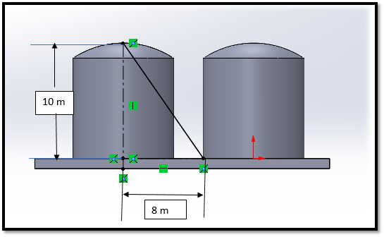
The figure 3 shows how the tanks measurement was taken. According to standards NFPA the distance between tanks should be from centre of one tank to outer surface of another tank. For analysis fixed roof tank were considered and the fuel inside the tanks was crude oil. According to standards the minimum distance was kept 8 m between the tanks. The crude oil when burnt generates a 350oC temperature. As crude oil is very volatile, so the distance should be that the fire on one tank does not ignite the fuel in other tanks. For this analysis Ansys CFD and static temperature was used. There are lots of mathematical model that are present to analyse situation like this but less CFD models.
- Tanks material
| Carbon Steel | Stainless Steel | Plastic | Fiberglass | |
| Price | ✓✓✓ | ✓ | ✓✓✓✓✓ | ✓✓✓ |
| Weight | ✓ | ✓ | ✓✓✓✓ | ✓✓✓✓ |
| Handle High Temperature | ✓✓✓✓ | ✓✓✓✓ | ✓ | ✓✓ |
| Handle High PSI | ✓✓✓✓ | ✓✓✓✓✓ | ✓ | ✓✓ |
| Corrosion Resistance | ✓ | ✓✓✓✓✓ | ✓✓✓✓✓ | ✓✓✓✓✓ |
Table 2: material Properties
As it shows in Table 4; there are several types of raw materials used in building oil tanks:-
- Carbon Steel Tank.
Ability to withstand high pressures and superior durability.
Ability to store products without cracking, melting or any other damage.
v Stainless Steel Tank.
They are resistant to corrosion
Withstand higher and lower temperatures
Costly and expensive.
- Plastic Tanks
The cheapest of four materials.
Not suitable for pressure maintenance.
- Fibreglass Tank
Are lighter than steel tanks due to their weight.
Offers the least possible expansion and shrinkage in hot, cold or stress.
7.3 Wind and Velocity Analysis
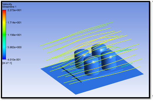
Using Ansys CFD first, the wind and velocity analysis were done. The reason for this study was to observe the behaviour of wind and velocity flow between tanks. Also, to find where turbulence occurs. Figure 4 shows the velocity analysis. From above figure, the maximum velocity occurs at the entrance point between the oil tanks. As an example, the above figure shows the wind movement in scenario one, while the wind speed considered in 15 m/s. The maximum velocity was seen to be 2.272 m/s, and the minimum velocity was observed to be 4.010e-1. However, by continuing with the rest of the scenarios, the following conclusions were drawn, as shown in table 5.
| scenario | Speed m/s | Velocity Max and Min between tanks. m/s |
| scenario 1 | 15 | 4.01 e-001 – 2.272 e+001 |
| scenario 2 | 20 | 5.362 e-001 – 3.02 e+001 |
| scenario 3 | 25 | 6.209 e-001 – 3.791 e+001 |
| scenario 4 | 30 | 7.769 e-001 – 4.549 e+001 |
| scenario 5 | 35 | 1.240 e000 – 5.360 e+001 |
Table 3: Velocity analysis outcomes
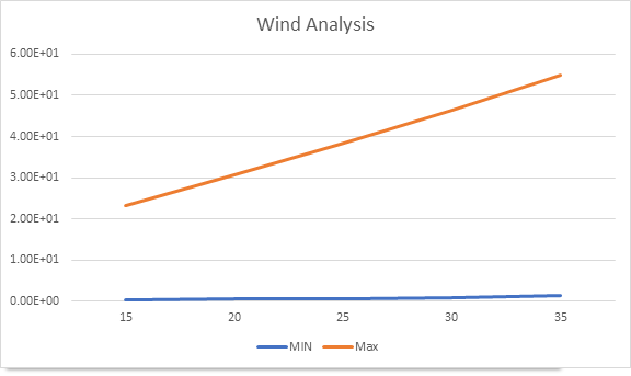
Finding and outcomes table 5 and graph 1
- I can be seen from the table and graph that as the wind speed increases the speed with the tanks of also increases drastically only if there is a difference of 5.
- The maximum speed at 35 m/s is 5.360e+001.
- The minimum speed at 35 m/s is 1.240 m/s.
- It shows as the wind speed increases the wind resistance decreases.
7.4 Pressure analysis
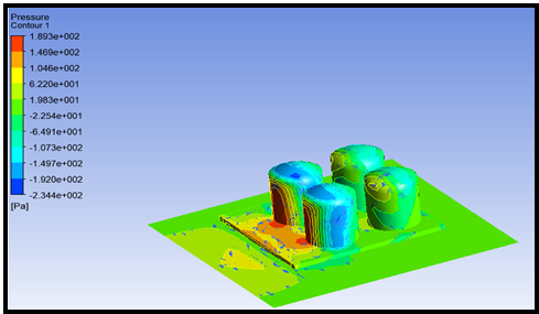
Then the pressure effect of the wind was studied, and the results are shown in figure 5. The maximum pressure was observed to be 1893e+2 which at the pint of the entrance from where the wind enters between the tanks. The maximum pressure was on the tanks at the starting because they interfere with the motion of mind most. As the tank top is curved, so the maximum value of pressure is reasonable. The minimum pressure was observed to be -2.344e+2. However, by continuing with the rest of the scenarios, the following conclusions were drawn, as shown in table 6.
| scenario | Results of the pressure Mix / Min
Pa |
| scenario 1 | -2.344 e+002 – 1.893 e+002 |
| scenario 2 | -4.169 e+002 – 3.367 e+002 |
| scenario 3 | -6.515 e+002 – 5.262 e+002 |
| scenario 4 | -9.381 e+002 – 7.576 e+002 |
| scenario 5 | -1.276 e+003 – 1.031 e+003 |
Table 4: Pressure contours analysis outcomes
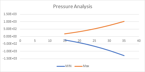
Finding and outcomes from table 6 and graph 2.
- It can see the change in pressure changes with the change in wind speed.
- The wind speed was increased by five every time.
- The values increase by the multiple of 2 every time accept the 4th scenario.
- In the 4th scenario, the values change drastically on both min and max.
- The pressure changes because it becomes difficult for the fast wind to overcome the resistance on tanks walls completely. The speed is too fast that the tank walls due tanks shape remain in their position.
- The cylinder shapes helped a lot to overcome the wind drag.
7.5 Flame Analysis ( Volumetric Rendering)
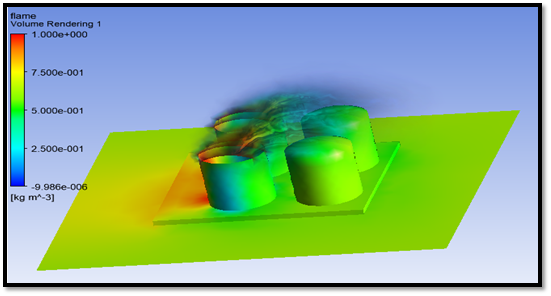
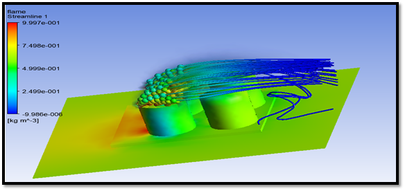
In this analysis, the motion of flame according to the wind motion was studied, and its effect on nearby tanks was studied. The results were satisfactory. Figure 6 shows the volumetric rendering. The flame was given a volume so that it can observe. The most volume of the flame is near the exhaust from the tanks. As the wind flows, the volume gets disperse in the atmosphere. The maximum density was observed near the tank, which was 1 kg/m3. As the smoke moves away, the hot gases disperse, and the density decreases, which can be seen in the blue region. The minimum density observed was -9.98e-6. Then by using stream lines mode, the behaviour of flame was studied as shown in figure 7:
7.6 Heat Transfer Analysis
- Temperature
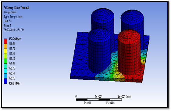
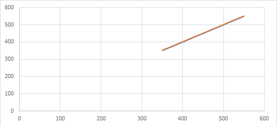
The heat transfer modes were selected through which heat can be transmitted to nearby tanks. For this heat transfer through convection and heat transfer through radiation was studied. The temperature of one cylinder was set to 350 oC was established, and that tank was set to be the source of heat transfer. That tank will emit radiations, and the heat from the tank will flow through convection also. The tank which was set as a heat source was the tank which was on fire. Concerning that tank, the effect of heat on nearby tanks was studied. For this, the results that were taken as the maximum temperature, radiant heat flux, total and directional heat flux.
The first analysis was of the temperature. Figure 8 shows the results which show that the tank which is on fire has little or no effect on nearby tanks. Only the tank that is on fire reached the temperature of 352oC .However, when the fire reached at 550oC, the tank got nearly the same effects. That’s mean the distance kept was a safe distance. The nearby tanks are on 352.01oC in 350C while got 551.01oC at 550oC. It noted from this analysis that the material should be steel as it can bear very high temperature. So, the tanks are safe. Generally, the melting temperature of steel is 1325oC to 1420oC depending on grade. Adding to that. table 7 and graph 3 below demonstrate the results of the five scenarios in different temperatures.
| Temp.
C |
Heat Flow
W
|
Radiation Temp.
C |
Total Temp.
C |
|
| 350 | 50000 | 350 | 350.01 – 352.26 | |
| 400 | 55000 | 400 | 400.01 – 401.97 | |
| 450 | 60000 | 450 | 450.01 – 451.74 | |
| 500 | 65000 | 500 | 500.01 – 501.54 | |
| 550 | 70000 | 550 | 550.01 – 551.38 |
Table 5: Temperature Analysis
7.6.2 Heat Flux.
| Temp.
C |
Heat Flow
W
|
Radiation Temp.
C |
Total Heat Flux
W/mm2 min |
Total Heat Flux
W/mm2 min |
| 350 | 50000 | 350 | 7.856e-011 | 4.013e-005 |
| 400 | 55000 | 400 | 6.9441e-011 | 3.5358e-005 |
| 450 | 60000 | 450 | 6.1793e-011 | 3.1335e-005 |
| 500 | 65000 | 500 | 5.5325e-011 | 5.7912e-005 |
| 550 | 70000 | 550 | 4.9821e-011 | 2.4927e-005 |
Table 6: Heat Flux
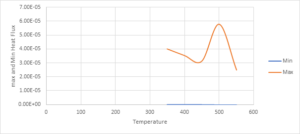
Table 8 and graph 4 are showing the fluctuation of the heat flux. Between 350oC to 450oC the heat decreases dramatically up to 3.1335e-005 W/mm2 and then reach in 500oC to 5.7912e-005 W/mm2. However, the heat flux dropped down to 2.4927e-005W/mm2 in the fifth scenario at 550oC.
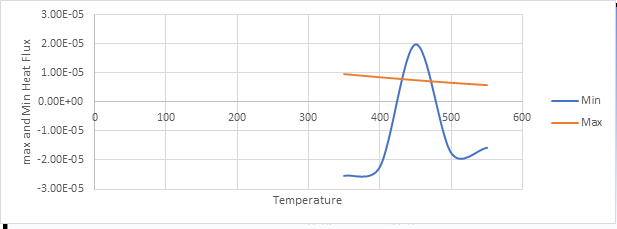
7.6.3. Directional Heat Flux.
In the figure 9 the directional heat flux is shown:
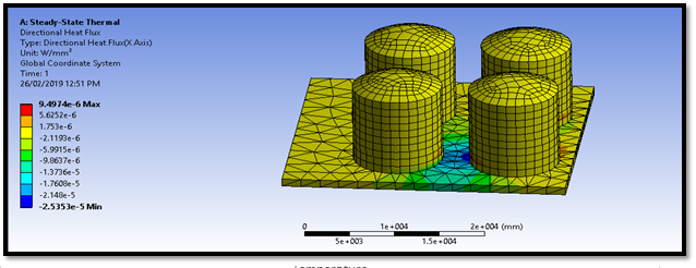
The heat flux direction was studied in x axis. It was observed that the maximum heat flux was 9497e-6 W/mm2 and minimum -2.5353e-5 W/mm2. So, it can be seen from results the distance is safe.
| Temp.
C |
Heat Flow
W
|
Radiation Temp.
C |
Directional Heat Flux
W/mm2 Min |
Directional Heat Flux
W/mm2 Max |
| 350 | 50000 | 350 | -2.5353e-005 | 9.4974e-006 |
| 400 | 55000 | 400 | -2.2294e-005 | 8.4393e-006 |
| 450 | 60000 | 450 | -1.9726e-005 | 7.4605e-006 |
| 500 | 65000 | 500 | -1.7554e-005 | 6.5679e-006 |
| 550 | 70000 | 550 | -1.5706e-005 | 5.7652e-006 |
Table 7: Directional Heat Flux
7.6.4 Radiation.
| Temp.
C |
Heat Flow
W
|
Radiation Temp.
C |
Radiation
W |
|||
| Emitted | Reflected | Incident | Net | |||
| 350 | 50000 | 350 | 3.4666e+006 | 310.77 | 3.4173e+006 | 49657 |
| 400 | 55000 | 400 | 4.7077e+006 | 303.49 | 4.6533e+006 | 54691 |
| 450 | 60000 | 450 | 6.2571e+006 | 289.12 | 6.1976e+006 | 59712 |
| 500 | 65000 | 500 | 8.1623e+006 | 300.16 | 8.0978e+006 | 64752 |
| 550 | 70000 | 550 | 1.0474e+007 | 306.69 | 1.0405e+007 | 69796 |
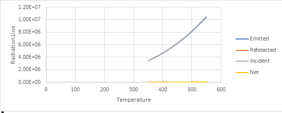
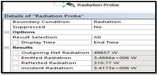
In figure 10 radiant the results of radiant heat flux are shown that the net radiation is 49657 W. The emitted radiation is 3.466e+06 W. Reflected radiation is 310.77 W and the incident Radiation is 3.4173 W. The results observed were in safe limit are this radiation cannot ignite the fuel in nearby tanks as they are made of steel and it requires lot of time to heat up.
Finding and outcomes from table 10 and graph 6.
- It can be seen clearly from the graph that the change in the temperature leading to a change in the values.
- The change in temperature does not have much effect as the temperature was increased by 50 in every scenario; the values do not change drastically.
- The total temperature of the cylinders can say remains the same.
- The results show that the Radiation emitted some tanks as not much the value is affected by changing temperature.
7.6.5 Total Heat Flux
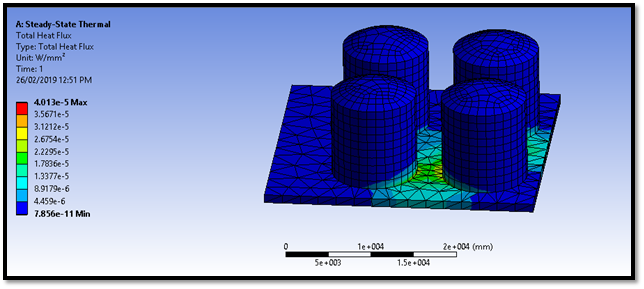
The figure 11 shows the total heat flux was 4013e-5 W/mm2 and it was near the tank on fire. While the tanks near the tank on fire had a heat flux 7.856e-11 W/mm2. So, it cannot be wrong to say that the distance is safe, and the fuel will not ignite.
Chapter 8: Safe separation distance standards between oil storage tanks
8.1. Safe separation distance.
| Flammable Material | Minimum Safe Distance
m |
Tank Layout | Dimensions
m |
Required area m2 |
| Gasoline | 25 | Square pitch | 108.25 | 22772.18 |
| LNG | 35 | Square pitch | 152.25 | 23180.06 |
| LPG | 45 | Square pitch | 195.75 | 38318.06 |
Table 9: Safe Distance
| Minimum Safe Distance for Above Ground Tanks (ft) | ||||||
| Tank Type | From Individual Tank Capacity (gal) | From the nearest Important Building on safe property | Nearest Fuel Dispensing Device | From lot line that is or can be built upon | From the nearest of any public way | Between tanks |
| Tank in Vaults | 0-15000 | 0 | 0 | 0 | 0 | Separate Compartments required for each tank |
| Protected above ground tanks | Less than or equal to 6000 | 5 | 0 | 15 | 5 | 3 |
| 60000-12000 | 15 | 0 | 25 | 15 | 3 | |
| Fire resistant tanks | 0-12000 | 25 | 25 | 50 | 25 | 3 |
| Other Tanks meeting the requirements of NFPA 30 | 0-12000 | 50 | 50 | 100 | 50 | 3 |
Table 10: Minimum safe distance
For SI units, 1 ft = 0.30 m; 1gal = 3. 8 L
8.2 Comparison
After carefully analysis and comparing the results with standards the distance kept between the tanks during analysis was safe. As it can be seen through analysis also that the flame did not had much impact on the nearby tanks. The material used was steel which can bear much high temperature. So according to standards minimum safe distance should be 5 – 10 m according to table 3.
Chapter 9: Conclusion and Recommendation
9.1. Conclusion
In this thesis using CFD analysis, the safe distance between the tanks was determined to verify that the distance kept was the safe distance or not. Another aim of this study is to identify the effect on nearby tanks in case of fire by analysing the heat transfer through radiation and the flow of wind between the tanks.
The study starts with high-quality steps.
- A pair of 4 tanks were considered and designed using solid works. A base was also designed. Keeping in view the standards the distance for analysis was 8 m and the diameter of the tanks was 15 m, and the height of tank was kept 10 m with a dome shape at the top. Fixed top cylinders were taken into consideration.
- Using CFD first wind flow was studied. Then flame behaviour was studied according to wind direction and what it will affect nearby tanks.
- The heat transfer through radiation and convection was studied. One of the tanks was considered on fire, and its temperature was set to 350oC, and its effect on near tanks was studied. For this analysis, Static temperature mode of Ansys was used. The temperature of the tanks was studied that showed the tanks were safe.
As a result of that, it can be concluded that:
- The major area of our study was to prove the safe distance is 8m and thus, it can say that 8 m is the safe distance if the material is steel. thus proved through CFD analysis.
- After analysing the material, stainless steel was considered the best material of tanks as it was lots of useful properties beside expensive. It can bear more heat and is also rustproof.
- it showed that the wind which flows between the tanks becomes turbulent at the end.
- It was observed that the density of flame was most near the tank on fire, and as it moves away, the gases get disperse, and the effect on near tank become less. So, the distance, according to this analysis, was safe.
- As the steel can bear very high temperature. The heat transfer through radiation and convection was showed the radiation emitted from the tank on fire could not ignite the fuel in other tanks.
9.2. Recommendation
After clear consideration it was observed some gaps like on field experiment and the results comparison with the CFD results were left in this study which can be done in future research. Some research can be done practically to prove the point. A practical setup can be setup which results can be compared with the simulation results. Then on-site observation can be done for the research rather than relying on the research papers results.
Peachy Essay essay services team offers a wide range of services including Engineering Writing Help:
– General Engineering Assignment Writing Services
– General Engineering Essay Writing Service
– General Engineering Dissertation Writing Service