


Advanced Analysis of Connections for steel roof structures at Elevated Temperatures
1. INTRODUCTION
1.1 Objectives
The objective of this study is to investigate the structural behavior of the steel joint for roof structure at elevated temperatures. The stainless steel is the most frequently used for roofing have higher fire protection. At elevated temperatures, stainless steel generally exhibits better strength and stiffness retention than carbon steel. The behavior of steel connection in the truss structure of a single story building is analyzed at elevated temperatures (Buchanan & Abu, 2017). The performance-based of design will be carried out to understand the mechanical properties and thermal properties of connections for roof structure at elevated temperatures.
This report discusses the analysis and design of a 30m span of 3D space truss steel structure. For the purpose of analysis, the structure is modeled with the software SAP2000 as a series of 3D structures, effectively simulating the path of forces in the structure.
2. REVIEW OF STRUCTURAL FIRE ENGINEERING
The purpose of Structural Fire Engineering is to design a building structure with suitable fire resistance. It deals with specific aspects of passive fire protection in terms of analyzing the thermal effects of fires on buildings and designing members for adequate load bearing resistance and to control the spread of fire.
It covers a wide range of knowledge and capabilities. The analysis and design of General Structural Fire Engineering should be involved in fire modeling, thermal analysis and structural analysis (Baddoo, 2008). A functional-structural fire resistance design will enable the structure to have a certain period of self-fire protection, and it can minimize the impacts to achieve the requirement of building regulations.
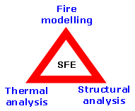
Figure 1
2.1 Comparison between Prescriptive Design and Performance-Based Design
2.1.1 Prescriptive Design
The prescriptive design is the traditional method which is straightforward for structural engineers for a third party to check, inspection and easy for authorities to enforce. Its regulations arise from work experience, through different several practices and the various incidents (Giuliani et al. 2013). The prescriptive design has integrated a series of standard codes to guide the work of design analysis.
2.1.2 Performance-Based Design
Performance-based fire designs of the structure provide the realistic prediction of steel in fire. This approach consists of heat in the steel roof structure, which enhances the knowledge in understanding of structure at elevated temperature (Rahnavard & Thomas, 2018). Performance-based design methods lead to increased design freedom from prescriptive code restrictions whilst maintaining safety. Appropriate and cost-effective fire safety measures are derived.
2.1.3 Finite element analysis
The finite element analysis as part of a performance-based structural fire engineering design. It is currently the most efficient method to simulate the structural response in the fire(Mikhail, 2015). This analysis can consider the highly non-linear behavior of structures in fire, including large displacements and non-linear temperature-dependent material properties, as well as the thermal expansion and contraction of the structural elements at elevated temperatures.
2.2 Case study- Collapse of steel structure under real fire
World Trade Center I
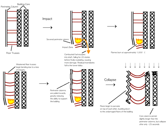
World Trade Center 5 was a nine-story office building constructed of a structural steel frame and composite floors. The roof and ninth floor were constructed using conventional steel framing; however, the eighth floor and those below were constructed using column trees. All of the structural members were fire-protected with a sprayed-on mineral fiber that provided a 2-hour fire rating to the floors and a 3-hour rating to the columns (Barnett, 2002).
In the investigation, one of the most important reasons for WTC structural collapse because of the Fire impact. When WTC at elevated temperature, the steel truss floor supports probably started to fail quickly from the flames and the center steel supporting columns severed by plane parts heated by the flames began to buckle, sag, warp and fail. Then the top part of the tower crashed down on the lower portion of the structure. This catenary action leads to collapse triggered the entire cascading collapse of the 110-story structure.
Figure 2 WTC 1 Collapse

Once the collapse begins, a large number of failing floors will flood the underlying floors, causing a series of progressive floor failures that accelerate as the sequence progresses(Ng and Ashraf, 2010). Then, most of the perimeter columns and possible cores did not have any lateral support, causing them to fall laterally outward and be pushed by more and more gravel. The result is that the walls are peeling off and away from the building for a distance and hit other adjacent buildings. When the bolt is broken, some of the connections are broken and many panels are randomly scattered.
The structural collapse appeared to be due to a combination of excessive shear loads on bolted connections and unanticipated tensile forces resulting from catenary sagging of the beams (Buchanan & Abu, 2017). There was local buckling of interior columns. This buckling was most likely due to a combination of fire-induced reductions in strength and a possible increase in stress due to restrained thermal expansion.
Figure 3 Simple representation of the collapse of the North Tower
2.3 Fire Test
Fire tests are the most common method of determining the fire performance of building components. Standard fire test is usually designed to assess the fire rating of a building element so it can meet the minimum performance criteria as set out in the regulation(Mikhail, 2015). It is a device that assesses the relative fire performance of different structural elements.
2.3.1 Standard Fire Resistance Test
The most widely used standard test specifications in steel are ISO 834 and ASTM E119(Giuliani et al. 2013). These guidelines for building fire safety design and do not represent the temperature-time history of an actual fire. Real fire is a function of many variables, such as thermal radiation, heat flux, fuel load, open area, and ventilation coefficient. ASTM E 119 is mainly used in North America, while ISO 834 is more used internationally.
2.3.2 Standard Fire Curves
The standard time-temperature curves from ASTM E119 and ISO 834 are compared in Figure 4
Figure 4 standard temperature-time curve
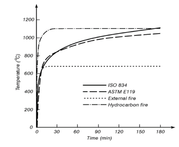
ISO 834 and ASTM E119 – Standard Time Temperature Curve
In an effort to better understand a building’s response to fire, standard temperature against time profiles have been developed. These profiles represent the air temperature within the compartment and are intended to be used as a comparative measure; they are not meant to be predictive (Yang et al. 2015). According to the Eurocode 1, ISO 834 equation used to describe the time against temperature relationship is:
TM = 345 x log10 (8t+1) + Ta °C [3]
Where, TM is the gas temperature (°C) at time t (min).
Ta is the ambient air temperature (°C).
The ATM E119 is similar to that of the ISO 834 and is described by the following equation:
T = 750[1 – e-3.79553t] + 170.41t + To [4]
Where, T is the gas temperature (°C) at time t (min).
Ta is the ambient air temperature (°C).
ASTM E1529 – Hydrocarbon Fire
Eurocode hydrocarbon fire curve is intended for use where a structural member is engulfed in flames from a large pool fire Temp, T (°C) in the hydrocarbon fire curve is given by T = 1080( e-0.167t e-2.5t)+ Tot is the time (min), To is the ambient temp. (°C)
As a result of failures of fireproofed steel members exposed to petroleum fuelled fires, the petroleum industry developed a new standard test curve (Yang et al. 2015). This curve is more representative of a sudden and intense shock, typified by petroleum fuelled fire or terrorist attack. The model imposes 158kW/m2 onto the surface and it is the instant nature of this heat that sets it apart from other models (Liew, 2008).
EN 1363-2 – External fire exposure curve.
This situation represents an external fire (typically a fire from an adjacent window or structure situated near the building) where the air temperature surrounding the wall facing the fire is given.
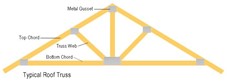
3. REVIEW OF TURSS STRUCTURES FOR ROOF
Trusses made of structural steel shapes are the common framing choice in structural systems that span over long distances or support heavy loads. In roof structure design, trusses are utilized as a means of achieving a high degree of spatial flexibility. As a result, certain trusses support large portions of buildings and are deemed to be of “critical” structural importance. Adequate attention is therefore essential to the fire resistance aspect of truss design.
3.1 Different Shapes of Trusses
3.1.1Simple truss
It made up of a single triangle, usually used to build a lighter roof, support the ceiling structure, or provide strength to the metal frame of the bicycle (the core of each modern bicycle design is the seat position, a single between the pedal and the handle) Triangles, as well as extra triangles that connect the core triangle to the rear wheel) and many other lightweight structures (such as airplanes).
Figure 5 Simple Truss
3.1.2 Planer Truss
A plane truss is defined as a two-dimensional framework of straight prismatic members connected at their ends by frictionless hinged joints and subjected to loads and reactions that act only at the joints and lie in the plane of the structure. The members of a plane truss are subjected to axially compressive or tensile forces. Most commonly, the graphic design consists of a single repeating pattern and is most commonly used to build roofs and bridges.
Figure 6 Plane Truss
3.1.3 Space Truss
The Space truss design can also be made in three dimensions, and it is the simplest and most commonly used space truss. Skeleton, three-dimensional structural works consisting of pin connected bars are called space trusses. They are characterized by hinged joints with no moments or torsi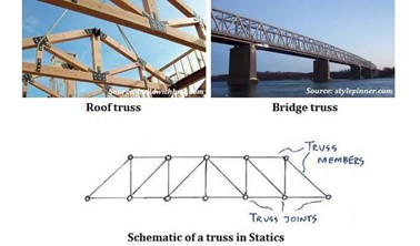
Figure 7 Space Truss
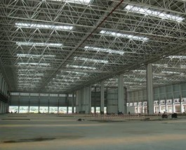
.2 Selection of Roof Shape- Space Truss Roofing
The steel space truss provides greater design and layout flexibility, as well as the possibility of evenly distribute the load to each rod and external constraint. With these features, it can be used to achieve complex geometries with a structural weight that is lower than any other solution.
Space frames are lightweight rigid roofing systems consisting of a series of connectors that join together the chords (or struts) and bracing members. Their strength derives from the rigidity of the triangle, with the flexing loads being transmitted as tension and compression loads along the length of each chord.
A space truss consists of members joined together at their ends to form stable three-dimensional structures. It is used to denote the structural system in which small linear members are arranged in three dimensions. The space truss structure as compared to the plane is three-dimensional nature both in assembly and in load carrying behavior.
Figure
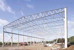
3.2.1 Advantages of the space truss
One of the most important advantages of a space frame structure is its lightweight. They are light, structurally efficient and use materials optimally. Most space frames are now constructed with steel or aluminum, which decreases considerably their self-weight. Furthermore, the structural distribution of trusses members caused the load transfer mechanism is primarily axial tension or compression. Consequently, all material in any given element is utilized to its full extent. This is especially important in the case of long-span roofs that led to a number of notable examples of applications.
Space trusses can be built up from simple, prefabricated units of standard size and shape. Hence they can be mass-produced in the factory, can be easily and rapidly assembled at the site using semi-skilled labor. So, it can have a lower construction cost.
A space frame is usually sufficiently tough in spite of its lightness (Selden et al. 2015). This is due to its three-dimensional character and to the full participation of its constituent elements. In structural design, space truss has great stiffness and inherent rigidity to resist a heavy load of the building, it can allow great flexibility in designing layout and positioning of end supports.
4. CONNECTIONS OF SPACE TRUSS ROOFING
Connections are normally made either by bolting or welding. Bolting is common in field connections since it is simple and economical to make. Bolting is also regarded as being more appropriate in field connections from considerations of safety. However, welded connections, which are easier to make and are more efficient, are usually resorted to in shop fabrications.
In Space Truss Roof design, It has many members are connected together in one joint. Bolted connection with clearance holes to transmit the load, the bolt must come into contact with one or other of the connected parts which allow slip in the connection, which caused not enough space for fixing by a bolt and it required additional plate system in design. So that, welded connections are more suitable to adopt in your proposed design.
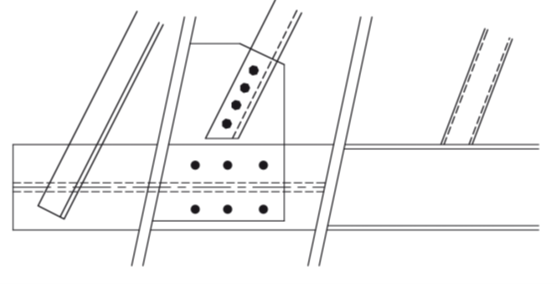
Figure 9 Too many bolts of truss connection
4.1 Welded Connections
Welded connections are direct and efficient means of transferring forces from one member to the adjacent member. Welded connections are generally made by melting base metal from parts to be joined with weld metal, which upon cooling form the connection. The welded connections in a majority of the cases may be categorized as fillet weld or butt welds
For lap joints, the ends of two members are overlapped and for butt joints, the two members are placed end to end (Rahnavard & Thomas, 2018). Most common joints are made up of fillet weld or the butt weld. Fillet welds are suitable for lap joints and Tee joints and groove welds for butt and corner joints. Butt welds can be of complete penetration or incomplete penetration depending upon whether the penetration is complete through the thickness or partial. Generally, a description of welded joints requires an indication of the type of both the joint and the weld.
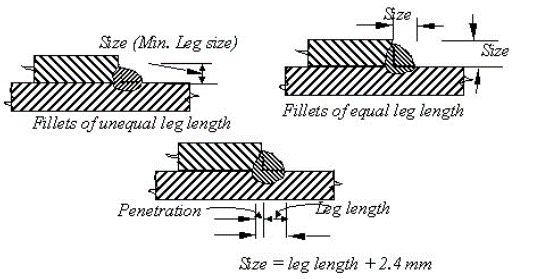
4.1.1 Fillet Weld
Fillet welds are classified a connection with end fillet is loaded in tension, the weld develops high strength and the stress developed in the weld is equal to the value of the weld metal. But the ductility is minimal. On the other hand, when a specimen with a side weld is loaded, the load axis is parallel to the weld axis. The weld is subjected to shear and the weld shear strength is limited to just about half the weld metal tensile strength. But ductility is considerably improved. For intermediate weld positions, the value of strength and ductility show intermediate values.
Fillet welds may be used for connecting parts where fusion faces form an angle of between 60°to 120. For angles smaller than 60°, fillet welds may be used but should be considered as partial penetration butt welds for design purposes. For angles over 120°, fillet welds should not be relied upon to transmit forces. A fillet weld should not be used in situations which produce a bending moment about the longitudinal axis of the weld if this causes tension at the root of the weld.
Figure 9 Fillet Weld
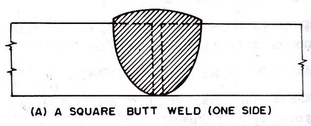
4.1.2 Butt Welds
The butt weld is normally designed for direct tension or compression. However, a provision is made to protect it from shear. The most critical form of loading is tension applied in the transverse direction. It has been observed from tests conducted on tensile coupons containing a full penetration butt weld normal to the applied load that the welded joint had higher strength than the parent metal itself (Selden et al. 2015). The yield stress of the weld metal and the parent metal in the HAZ (Heat Affected Zone) region was found to be much higher than the parent metal. The butt weld is normally designed for direct tension or compression. However, a provision
Full penetration butt welds
The design resistance of a full penetration butt weld should be taken as equal to the design resistance of the weaker of the parts joined. Guidance on throat size of partial penetration butt welds in BS 5950-1, clause 6.9.2 is applicable.
Figure 10 Butt weld
Partial penetration butt welds
Partial penetration butt welds may be used to transmit shear forces. They are not recommended in situations where they would be subjected to tension. The resistance of a partial penetration butt weld may be determined as for a deep penetration fillet weld. The throat thickness of a partial penetration butt weld may be taken as the depth of penetration that can be consistently achieved, as determined by procedure trials. In the absence of procedure trials, the throat thickness can be assumed to be the depth of preparation less 3 mm.
4.2 Design of Welds
4.2.1 Design of fillet weld
The design strength of a fillet weld shall be based on its throat area.
fwd = fwn / γmw in which fwn = uf/3
Where fu = smaller of the ultimate stress of the weld and the parent metal
γmw = partial safety factor (=1.25 for shop welds and = 1.5 for field welds)
The design strength shall be reduced appropriately for long joints as prescribed in the code. The size of a normal fillet should be taken as the minimum leg size.
Figure 9 Fillet welds of members
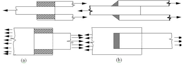
Design of butt welds
For butt welding parts with unequal cross sections, say unequal width or thickness, the dimensions of the wider or thicker part should be reduced at the butt joint to those of the smaller part. This is applicable in cases where the difference in thickness exceeds 25 % of the thickness of the thinner part or 3.0 mm, whichever is greater(Rahnavard & Thomas, 2018). The slope provided at the joint for the thicker part should not be steeper than one in five
Figure 10 Butt welding of members
5. MATERIAL PROPERTIES
5.1 Stainless Steel
Stainless steel is an alloy of Iron with a minimum of 10.5% Chromium. Chromium produces a thin layer of oxide on the surface of the steel known as the ‘passive layer’. This prevents any further corrosion of the surface. Increasing the amount of Chromium gives increased resistance to corrosion.
Stainless steel also contains varying amounts of Carbon, Silicon and Manganese. Other elements such as Nickel and Molybdenum may be added to impart other useful properties such as enhanced formability and increased corrosion resistance (Selden et al. 2015). The Chromium in the alloy forms a self-healing protective clear oxide layer. This oxide layer gives stainless steels its corrosion resistance.
Figure 11 Stainless Steel Classification and Grades
5.2 Material Grades
Design values of the mechanical properties are discussed in Section 2.2.2. BS EN 10088-2 covers the grades used in most construction applications. (It partly replaces BS 1449-2[13], which also covered heat-resisting steels.) The applicable standards for dimensional tolerances are specified in BS EN 10088-2. The designation systems adopted in BS EN 10088 are the European steel number and a steel name.
5.3 Mechanical Behavior and Design Values of Properties
Basic stress-strain behavior
The stress-strain behavior of stainless steel differs from that of carbon steels in a number of respects. The simplest form of the stress-strain relationship is two-straight lines, where the elastic modulus and yield strength are the only information needed to describe the behavior of steel members
The stress-strain behavior of stainless steel differs from that of carbon steels in a number of respects. The most important difference is in the shape of the stress-strain curve. Whereas carbon steel typically exhibits linear elastic behavior up to the yield stress and a plateau before strain hardening, stainless steel has a more rounded response with no well-defined yield stress as figure 12.
Stainless steel ‘yield’ strengths are generally quoted in terms of a proof strength defined for a particular offset permanent strain (conventionally the 0.2% strain), as indicated in figure 12, which shows typical experimental stress-strain curves (Banovic & Siewert, 2008). The curves shown are representative of the range of material likely to be supplied and should not be used for design. For 1.4301 (304) and 1.4401 (316) steels, the two curves shown indicate the extreme values from a series of tests and thus they represent a scatter band.
Stainless steels can absorb considerable impact without fracturing due to their excellent ductility (especially the austenitic grades) and their strain hardening characteristics. The work required to fracture the material is proportional to the area under the stress-strain curve.
Figure 12 Typical stress-strain curves for stainless steel and carbon steel
As the figure is shown, there are no limitations on thickness in relation to brittle fracture apply to stainless steel. On the other hand, the limitations for carbon steel are not applicable due to the superior toughness of stainless steel. Stainless steels can absorb considerable impact without fracturing due to their excellent ductility and their strain-hardening characteristics.
5.4 Behaviors in Fire
EN 1991-1-2 gives the thermal and mechanical actions on structures exposed to fire. Fire is designated an accidental design situation in the Eurocodes. EN 1990 gives combinations of actions for accidental design situations and recommends that the partial factors for actions are taken as 1,0. EN 1993-1-2 recommends that the partial material safety factor γM,fi for the fire situation should be taken as 1, 0(Lu et al. 2017).
The performance requirements of a stainless steel structure that may be subjected to accidental fire loading are no different to those of carbon steel, namely:
- Where mechanical resistance in the case of fire is required, the structure should be designed and constructed in such a way that it maintains its load-bearing function during the relevant fire exposure.
- Deformation criteria should be applied where the means of fire protection, or the design criteria for separating elements, require the deformation of the load bearing structure to be considered. However, it is not necessary to consider the deformation of the load-bearing structure if the fire resistance of the separating elements is based on the standard fire curve.
6.0 THE POST-ASSESSMENT OF STRUCTURAL STEEL
It is possible to do visual observations to evaluate the integrity of structural steel that is subjected to high-temperature levels. Research indicates that at 230℃, wood will start to burn while at 600℃ the surface of concrete begins to spall. Based on studies, structural steel will attain a rough and eroded appearance on the surface when the temperature goes beyond 650 ℃. Nevertheless, the different type of paints applied to structural steel is critical in explaining the temperature in the fire compartment. Higher temperatures of over 300℃ will cause the paint to change the color and blistering occurs. For steel members that are subjected to open fire, there will be flaking-off of the paint.
Figure 13: Paint layer under complete burning on the structural element of steel
The level of damage on structural steel can be provided from the post-fire analysis of the geometry member of steel based on deformations and elongations. There are three categories of steel members that are exposed to high temperatures (Bronzova & Garifullin, 2016). The first group includes the strength members which cannot be affected by exposure to fire and it becomes difficult to make visual observations to members having small strains. The second group involves members whose deformations are visible and can be well straightened through heating. The third group is composed of members that undergo high deformation and distortion whereby replacement acts as the best solution rather than repairing. Extreme temperatures have the capability of causing excessive deformations on steel members due to reduced load bearing capacity and buckling. Also, steel members have the capacity to develop longitudinal or local transversal cracks.
Figure 14: Bottom chord of a truss girder under local deformation due to elevated temperatures
Figure 15: Truss girder having a longitudinal crack as the chord bottom
Figure 16: A truss girder with transversal crack
The test is suitable in cases whereby there is a large deformation in the steel members. Through ultrasonic testing, it is possible to examine the internal flaws that are formed after structural steel is exposed to fire. In destructive testing, it entails removing samples from the steel members under high temperatures to get data on steel ductility, Young’s modulus, tensile strength and yield strength.
6.1 Failure Mechanism
Steel structures and members can undergo failure mechanism due to failure temperature, but there is also a possibility of it occurring before attainment of the critical temperature. A steel member under fire will attain the critical temperature when it is in safety conditions, it fails to support the load. The failure mechanism can be influenced through various parameters like structural steel’s mechanical properties which can highly decrease when exposed to fire, steel members’ connection and the masivity factor(Banovic & Siewert, 2008) Based on Eurocode 3, it has presented a detailed review of the structured steel behavior at extreme temperatures. From figure 17 below, temperatures below 400℃ do not facilitate any reduction on yield strength. The modulus of elasticity is influenced by temperatures that are over 100℃. It is understood that the yielding strength of structural steel at 600℃ is responsible for 42% of the initial value while Young’s modulus decreases to 30%. High temperatures cause thermal elongation of steel members. When restrained, there is the development of internal forces and moments. Exposure to fire causes full plasticizing of sections of steel or failure prematurely because of the local instability.
Figure 17: The reduction factors for the proportional limit, Young modulus and yield stress
It is understood that industrial buildings that lack floors are capable of limiting the lateral displacements which amount to other forms of failure mechanisms.
Figure 18: Horizontal portal frames under failure mechanisms
Figure 19: Pitched portal frames under failure mechanisms
On industrial steel buildings, the failure mechanism is dependent on the conditions of fire, connections and geometry. According to studies on the behavior of portal frames with pitched and horizontal roof subjected to high temperatures, there was the identification of failure mechanisms as illustrated from figure 18 and 19. It is noted that the horizontal frames experienced a failure mechanism that is local or beam mechanisms while pitched roof frames experienced global mechanism (Baddoo, 2008).
Steel members that do not have sufficient restraint suffer extensive deflection which is developed from their thermal strain. For large span buildings, the best solution is the use of lattice girders. Truss member’s joints are hinged, but there is a restrained axial displacement in the joints. Thus, elongation developed through thermal strain cause local buckling or even amount to global buckling of the whole girder which is considered as out of plane failure.
Figure 20: Truss girders in-plane buckling after exposure to fire
Figure 21: Truss girders out of plane buckling after exposure to fire
Figure 20 and 21 above, were taken after steel members were exposed to fire and it indicates two forms of truss failure mechanism which are in-plane and out plane mechanisms after fire exposure. It is evident that trusses having hollow sections experience more effect when subjected to high temperatures when compared to the I-beams. This is due to the internal members having a smaller area of cross-section, lengths of buckling and slenderness factor. The unprotected steel members suffer failure mechanism due to the robustness of steel structure. The structural redundancy facilitates the examination of the steel structure collapse mechanism under high temperatures. Having a high redundancy of the steel structure causes the development of plastic hinges until the structure collapses (Bronzova & Garifullin, 2016). Majorly when considering the single story steel buildings, the collapse of one steel member does not cause the whole structure to collapse. It has to be understood that there is no uniform temperature distribution when in the fired compact on a building. During combustion, the columns are directly affected by those materials on the floor level. The purlins, girders and bracing elements are exposed to heated air.
7.0 METHODOLOGY
7.1 Fundamental Behavior of Steel Connections under Fire Loading
Based on the ASTM E119, it has conducted experimental testing for building components to determine the standard fire ratings. Nevertheless, it is difficult and expensive to perform standard fire tests of loaded columns due to the application of massive axial loads together with elevated temperatures. There are a variety of column testing furnaces that are used in engineering. The fundamental behavior is described as the response of the axial force-moment-curvature-temperature (P-M- Φ -T) of the section of failure of steel beam-columns and those which are exposed to high temperatures simulating fire loading. The concept is relevant in providing guidelines for making structural performance-based designs in building structures for steel members under realistic fire loading scenario. It is noticed that the condition of structures of steel building under fire loading is dependent on the performance of extreme temperatures of the steel members, mostly columns. By using the 3D finite element models (3D FEM), it helps to investigate the behavior of steel columns under fire.
7.1.1 Test Program
The experimental procedure involved the two main parts which included the steel columns and the steel-beam columns under loadings of fire. In this experiment, it focused on examining;
- The displacement of lateral load responses of bean columns of steel at an extreme temperature
- The behavior of axial force-moment-curvature temperature at the base segment of steel beam-columns.
- Steel columns stability subjected to extreme temperatures.
Figure 22(a): Test Setup
Figure 22 (b): Layout instrumentation for W10×68 tests of beam-column
7.1.2 Beam-Column Tests
Figure 13 above illustrates the test frame of experiments of beam columns. The specimens for testing comprised of cantilever beams of W10×68 which are fixed at the base and free at the top. There was an equal length of a specimen of 2.5m from the foundation to the free end. There was the design of two concrete blocks of 914mm ×914mm×914mm that clamped the bottom part of the specimen. The specimen test length was made as 1.6m. There was testing of specimens of steel beam-columns at ambient to investigate the test setup and to relate it to the behavior of the tested specimen at extreme temperatures.
A hydraulic cylinder of 1800 KN was used to provide axial loading at the specimen’s top. There were several preliminary tests that were done to reduce the eccentricity of the load. A hydraulic cylinder of 450-KN facilitated the application of lateral loading at the specimen. There was a steel bearing half-cylinder that was placed at the lateral force position to mitigate the flanges from failing and facilitate free rotation at the ends. There were two tension rods of 64 mm diameter that were made to resist reaction from an axial load of 2700 KN. The bottom portion of the tension rods was linked to clevis and pin to encourage rotation in lateral loading direction without forming undesired restraints.
A digital imaging system was incorporated to measure curvature, average strains and deformations of the heated sections (Lu et al. 2017). According to figure 22 (b), the target points of the camera were located as indicated. The top and bottom rows distance of target points were equal to 330mm. A 75mm was used as the focal length of each lens of the camera. There was a perpendicular installation of digital cameras to the target points to ensure a negligible effect of lens distortion on the displacement measurement. There was programming of the digital cameras such that it captures images after every second.
Based on figure 13 (a), a group of cameras captured images of the target movement points and saved them in the system of data acquisition. Post-processing of the stored images followed to determine the lateral and axial displacements in real units to calculate the average strains of longitudinal, curvature and the heated region base rotation. In the ambient test, data displacement through digital cameras was associated with the other voltage-base sensors. The values of average strain captured by the imaging system and strain gauges were similar.
Figure 22 (b) illustrated the layout of instrumentation and the displacement transducers at different points within the length of the specimen. The clevis-pin assemblies were used to mount two rotation transducers. The welding of K-type thermocouples at the specimen surface followed to give temperature records at failure segments. Various PID controllers were used to regulating the heaters individually. The (T-t) curve denoting the pre-determined temperature-time of the specimen was programmed at each controller of PID to facilitate uniform heating of the base segment. During the test, there was monitoring of the temperatures from the heat developed by heaters.
The procedure was as follows;
- The application of an axial load (P/PO= 0.3) at the specimen top. The load was ensured to be constant during the entire test.
- The application of radiant heat at the failure segment or the surface at the base segment by ceramic fiber heaters. The regulation and monitoring of power rates of the heaters followed until there was a recorded average temperature of 300℃ at the failure segment. After stabilization of the surface temperature, there was application of an increased monotonically lateral load around the free end up to flexural failure.
Figure 23 (a): Test setup
Figure 23(b): Layout instrumentation
Figure 23 (c): Records of temperature-time for column tests W8×35
7.1.3 Column Tests
Based on figure 23 (a) indicates the test-frame that is self-reacting which was designed to perform column tests. The test frame precisely facilitates the performance of column tests under different parameters and axial load reaching a maximum of 4000KN. Four concrete blocks measuring (1524 mm x 610 mm x 610 mm) were used to support the whole setup. At the blocks, steel plates of 9mm thick and smooth surfaces were placed along with Teflon machine grease to reduce friction between the concrete surfaces and at the reaction beams’ bottom edges. Level surveyors and hydro-stone paste were used during the assembling of test frame.
A hydraulic cylinder of 5000KN was used for axial loading. Two tension rods of high strength and having 76 mm diameter were made to persist the reaction produced by the axial load of 4000 KN. There was the assembling of matching saddles and half-cylinder steel bearings to the reaction beams to prevent the tension rods from experiencing undesired bending (Banovic & Siewert, 2008). There was conduction of different preliminary tests to reduce the eccentricity load. Ceramic fiber heaters were used to supply radiant heat to the columns. The column length that was exposed to extreme temperatures was equal to 2000mm. There was the fabrication of adjunct stand to enable installed heaters to be 1 cm from either side of the specimen. The columns lateral movement due to axial loading was not affected by the heaters.
Based on figure 23 (b), it indicates the layout of the instrumentation of column tests. Along the specimen length, there were displacement transducers that performed ambient tests. At the column ends, there was the mounting of two rotation transducers. Then there was welding of K-type thermocouples to the specimen to record temperatures of bare steel surface as indicated in figure 23 (c). The PID controllers controlled the heaters. At the top of the steel web, there was placing of the glass wool insulation to ensure there was no exposure of radiant heat.
The following test procedure was performed consecutively;
- A 133KN initial axial load was applied to facilitate horizontal alignment of the specimen. There was the installation of strain gages around the mid-section of the columns to investigate the load eccentricity.
- After maintaining the initial axial load through the hydraulic controller, the specimen was put under thermal loading through four-radian ceramic fiber heaters. PID controllers were used to monitoring the surface temperature of steel.
- After attaining a 300℃ average temperature, there was a monotonic application of axial load until the column specimen attained an ultimate strength.
8.0 TEST RESULTS AND ANALYSIS
8.1 Beam-Column Tests
The test results obtained indicated a typical relation of the fundamental behavior of specimen W10×68 which was investigated at ambient temperature and then put under the temperature of 300℃ of steel surface. It was ensured that the maintenance of constant axial loading (P/PO =0.3). When there was the attainment of a temperature of 300℃ at the base segment of the steel surface, there was subjection of lateral load to develop a 160 mm lateral displacement (Bronzova & Garifullin, 2016). Moreover, examination of test parameters like (temperature gradient, the temperature of steel surface, the specimen’s materials and geometric properties, axial load level and fireproof thickness) on the condition of steel-beams columns. It was observed that with the increase of applied lateral load, the yielding transferred to the heated region of the base segment to develop the plastic hinge mechanism. The displacements of axial (vi) and lateral (ui) of the bottom and top heated region was evaluated through the digital imaging system. The curvature (Φ) and average strain (εavg-j) of the segment failure were tabulated using (vi) and (ui). The test setup had flexibility that caused rotation of rigid-body of the base specimen. Therefore, the calculated lateral displacements beside the length of the specimen were varied by deducting the lateral displacement due to the rotation of the base.
Figure 24 (a): The measured response of F-Δ-T
Figure 24 (b): W10X68 beam-columns producing M-Φ-T response
Figure 24 (a) illustrates the usual (F-Δ-T) response which is the lateral force-deformation-temperature of the bean columns W10×68 which are exposed to (P/PO of 0.3) as axial loading together with two separate thermal loadings of T and ambient of 300℃. Initially, the lateral response denoted by F-Δ is linear then there is the non-linearity during the increase of applied lateral load. The lateral load capacity of the specimen is maintained due to the increased lateral displacement, while yield develops and moves to the base segment. Under extreme temperatures, there is the observance of nonlinear behavior during early loading stages.
From figure 24(b), it shows the typical relations of the responses of moment-curvature-temperature of the heated region or failure segment between the experimental results and the 3D FEM models. At ambient temperature, the flexural stiffness that is measured aligns with the obtained results from 3D FEM. Nevertheless, the moment capacity of plastic is higher than that of 3D FEM model. The implication is due to the formation of material properties of elastic and perfect plastic by the 3D FEM models. The other reason is the inconsistency between the nominal properties materials and that of measured value both at ambient temperature utilized by the 3D FEM models.
With the increase of surface temperature, there is a significant decrease in flexural stiffness during the initial stages of loading. Also, the moment capacity of plastic is not highly impacted by the variation between the material properties of actual and nominal. By comparing figure 24 (b), it shows that at 300℃ the assumed material properties act better with the test specimen as compared to those at a temperature of ambient. The reason is there is greater yield stress of the actual material which exceeds 345 Mpa at ambient temperature, however, at a temperature of 300℃, the yield stress reduces to the assumed value of 212 Mpa.
8.2 Column Tests
The tests results obtained indicated the relationship between the specimen at a temperature of 300℃ of steel surface and the fundamental behavior of the column W8 ×35 tested at ambient temperatures. Further examinations of the test parameters such as rotational restraints, steel temperature and the ratio of slenderness were also reviewed.
Figure 25 (a): The response of P – Δ at ambient
Figure 25 (b): The response of P – θ at temperature, T= 300℃
From figure 25 (a), it gives the results of W8×35 column specimen whereby the calculated and measured responses of the axial load-displacement were compared. The slenderness ratio denoted by (L/r) was determined to be 67(Giuliani et al. 2013). It has to be understood that there was no investigation of the response of P-Δ at a temperature of 300℃ as;
- A trial experiment of the ambient column test was carried out to determine the condition of the self-reacting test frame.
- Creation of displacement transducers layout to evaluate the column deformation at extreme temperature was still in progress.
It is noted that at ambient temperature, there was a correlation between the measured axial stiffness with the gathered results from 3D FEM. There is a small variation between the calculated and measured axial load capacity. This is because the 3D FEM model does not undergo strain hardening and it becomes elastic and perfect plastic. Also, there would be variations between the nominal material properties and the measured ones at ambient temperature for the 3D FEM model.
Figure 25 (b) has related the response (P-θ), axial load-end rotation of heated specimen of column W8×35 at a temperature of 300℃ between the experimental results and the 3D FEM model. The solid lines in the figure indicate the rotations recorded at every column end. The positive values show the measured rotation at the hydraulic cylinder while the negative values show the rotation recorded at the extreme end (Lu et al. 2017). According to the specified Euro code, the 3D FEM model was developed from the material properties of temperature-dependent steel. By having a 400 Mpa steel yield strength being applied in the 3D FEM, the column axial load capacity that was measured at a temperature of 300℃ was found to be 1400 KN. Also, the P-θ response that was measured agreed with the obtained results of 3D FEM. In figure 16(b), the cooling by mistake triggered a slight discontinuity.
It was evident that the experiment was successful in examining the structural behavior of the beam-columns and columns at extreme temperatures. The P-M-Φ-T, P-Δ-T, and P-θ-T that denoted the behavior of steel columns were compared to the structural behavior of the results from the 3D FEM model. It was found out that the increase of steel surface temperature caused a decrease of flexural stiffness which was more significant during the initial stages of loading. There was minimal effect on the moment capacity of plastic at extreme temperatures based on the variation from the actual and nominal properties of materials than at ambient. The other finding was that the P-θ response that was measured conformed to the results gathered from the 3D FEM when using the material properties of Eurocode steel. Through the P-θ response, it was evident that the setup managed to conduct column tests while also ensuring supported end conditions.
CONCLUSION
The purpose of Structural Fire Engineering is to design a building structure with suitable fire resistance. It deals with specific aspects of passive fire protection in terms of analyzing the thermal effects of fires on buildings and designing members for adequate load bearing resistance and to control the spread of fire. The prescriptive design is the traditional method which is straightforward for structural engineers for a third party to check, inspection and easy for authorities to enforce. Its regulations arise from work experience, through different several practices and the various incidents. Performance-based fire designs of structure provide the realistic prediction of steel in fire. This approach consists heat in the steel roof structure, which enhances the knowledge in understanding of structure at elevated temperature. Standard fire test is usually designed to assess the fire rating of a building element so it can meet the minimum performance criteria as set out in the regulation. The most widely used standard test specifications in steel are ISO 834 and ASTM E119. These guidelines for building fire safety design and do not represent the temperature-time history of an actual fire. In roof structure design, trusses are utilized as a means of achieving a high degree of spatial flexibility. As a result, certain trusses support large portions of buildings and are deemed to be of “critical” structural importance. The steel space truss provides greater design and layout flexibility, as well as the possibility of evenly distribute the load to each rod and external constraint. A space truss consists of members joined together at their ends to form a stable three-dimensional structure. It is used to denote the structural system in which small linear members are arranged in three dimensions. Extreme temperatures have the capability of causing excessive deformations on steel members due to reduced load bearing capacity and buckling. Also, steel members have the capacity to develop longitudinal or local transversal cracks. Steel structures and members can undergo failure mechanism due to failure temperature, but there is also a possibility of it occurring before attainment of the critical temperature. A steel member under fire will attain the critical temperature when it its safety conditions, it fails to support the load. Steel members that do not have sufficient restraint suffer extensive deflection which is developed from their thermal strain.