


Surge tanks
Surge tanks calculate the combined shrinkage, meter factor, and liquid flow rate. They are also employed as a second-stage separator, and an automated pressure control valve on the gas outlet maintains a constant back pressure. Surge tanks can also be utilized as storage. The tank should be equipped with high and low-level alarms to prevent leakage (Gil, 2019).
Surge tanks are used in hydropower facilities with lengthy water conduits to minimize pressure forces during significant water mass acceleration. They are built as intermittent water reservoirs near the turbines, either open to ambient air or as a closed volume filled with compressed air. The surge tanks shorten the length of the accelerated water column and hence the accompanying pressure forces. This decrease is required to restrict structural components’ design pressure and enable turbine speed control (Peng, 2019).
Closed surge tanks for hydropower plants can be built as rock caves or steel tanks filled with pressured air and are used where terrain or other circumstances make open surge tanks linked to atmospheric air impractical.
There are two primary advantages of adopting a closed surge tank over an open type:
- More freedom in powerhouse placement and a shorter tunnel system
- A shorter distance between the surge tank and the turbine means more efficient control.
The shift from fossil to renewable energy raises the demand for flexible hydropower facilities to counter the highly variable output of wind and solar. Surge tank design becomes increasingly significant as power plant size grows due to increased water masses and pressure pressures. Additional frequent start-stop operations amplify the necessity of the surge tank, and more surge tank research is critical to prepare for future issues (Rezghi, 2019).
Recent research has enhanced mathematical models and offered a better understanding of closed surge tanks’ complicated hydrodynamic and thermodynamic processes. Enhanced computer models in conjunction with physical-scale models that may be used to build best and run these have been created and will be improved further (Ritcher, 2019).
The most common types are compressor surge tanks and bladder surge tanks.
Compressor surge tanks are enclosed devices with open contact between the water at the tank’s bottom and the air at the tank’s top. A compressor provides the air. The pressure of the air and water is equalized when the requisite air volume is pushed into the tank. Some air is absorbed as the water moves in and out of the tank. This implies that the volume and pressure of the air must be monitored and regulated. When adding air, the compressor must be permanently attached. This entails intricate controls. Injecting air into the pipeline is an unfortunate byproduct.
Many of these problems are solved by bladder surge tanks (Righi, 2018).
They require practically minimal upkeep since the water and air are separated, no air is absorbed. This implies that there is no need for a compressor or a control system to top it off. This also implies that you are not introducing air into your pipeline. The quality of the bladder is critical to the proper and dependable long-term operation of these tanks. Several companies are now making bladders with lengthy lifespans (Salimi, 2020).
Air valve design
Air valves have traditionally been used to remove air from water pipes and inject air when a pipeline is drained to avoid dangerous vacuum situations. With the advancement of air valves, rapid intake, and low-velocity exhaust design, they have garnered more attention as possible water hammer reduction devices. They are becoming more widely adopted for this purpose (Triki, 2020).
Such two-stage air valves contain a big aperture and a smaller orifice triggered by differential pressure and “switch” over when the differential pressure reaches a sufficient level to activate the orifice (Wan, 2018).
Operation
- In a pump station, a two-stage air valve is a surge suppressor.
- When a pump fails, column separation occurs. As a result, there is low pressure (or even a vacuum) downstream of the pumps. The high water hammer slam is caused by the quickly reversing water column that fills this low-pressure zone.
- A two-stage air valve on the pump’s delivery side would rapidly enable air into the pipeline to compensate for the low pressure.
- If the water column were reversed, the air valve would allow this air to be evacuated again.
- If the water column reverses too quickly, the high differential pressure (at the air valve) leads the air valve to switch to the smaller orifice, resulting in a slower exhaust flow rate and a slower rate at which the water column reverses. This lessens the pounding on the pump’s check valve.
This means that properly designed two-stage (or non-slam) air valves can perform the same job as costly surge tanks and eliminate air from the pipeline.
These two-stage air valves can also be utilized at the following pipeline locations.
At low-pressure places near the hydraulic grade line, column separation is joint even during regular pipeline operation (Wan, 2019).
The pipe filling procedure might be uncontrolled and overly quick at times. Standard air valves would then evacuate the air at an excessively high velocity, resulting in an air valve slam which can cause catastrophic damage to the air valve and the pipeline and components nearby.
Reason as to why pipeline builders use air valves
In certain circumstances, the column separation volume is so enormous that an excessive number of air valves are required to overcome the low-pressure scenario.
In other circumstances, a relief function (rather than limiting a low-pressure occurrence) is required, which can only be fulfilled by a surge relief valve or surge tank.
Air valves were once considered unreliable and incapable of performing the critical role of reducing water hammers. This is warranted because there are a lot of low-quality air valves on the market. They are considered high-maintenance goods. Most air valves begin leaking after a short operation, and operators frequently block the isolating valves under the air valve to arrest the leak!
Finally, most two-stage air valves do not flip at a low enough difference (Fersi, 2018).
Issues addressed by air valves
- They are dependable. Because of its excellent seal design, they come with a 10-year leak-free warranty.
- Their 2-stage air valves have a substantially lower switching point than most others. Surge 2000 software creators affirm that it is highly efficient.
Surge tanks in hydropower plants
The surge tank primarily aims to reduce water’s pounding impacts. A quick increase in penstock pressure might result in a rapid drop in generator load demand. With a quick drop in load demand, the gates of turbines, which admit water within the turbine, immediately close owing to governor action. The pressure in the Penstock is quickly boosted due to this action, resulting in the beneficial water-hammering effects. The excessive degree of pressure might potentially cause Penstock to explode. With the abrupt rise in load, the governor valves open, allowing more water into the turbine (Garg, 2020).
This process causes a vacuum in the Penstock, resulting in negative water-hammering consequences. In summary, the Penstock must have positive water hammering effects when the governor valves are closed and hostile water hammering effects when the governor valves are opened (Gugo, 2018).
Surge tanks are required in properly operating hydroelectric power facilities to protect the Penstock from such water-hammering impacts. The surge tank is installed in the system between the nearest power station and dam. Surge tanks absorb surges created by the water in the Penstock due to the generator’s abrupt loading and emptying. As water velocity in the Penstock decreases due to the closure of turbine valves, the amount of water in the surge tank decreases until its motion is damped by friction. On the other hand, the surge tank provides acceleration when the water accelerates inside the Penstock. The water level in the surge tank drops and changes dramatically due to surge absorption (Ritcher, 2018).
Penstock
Penstock refers to pressure pipes transporting water from the surge tank to the hydropower house. Penstocks are expensive and an essential element of the water conductor system since they are intended for maximum water pressure, including water hammers caused by the rapid closing of the intake valve. The penstock material, which might be steel, glass fiber reinforced plastic, or concrete, is chosen depending on the ground condition, accessibility, weight, cost, weather condition, corrosion, and other factors. Depending on the ground contour, penstock material, ambient temperature, and environmental needs, they are erected above or below ground (Salimi, 2020).
The layout of the Penstock is determined by topography, site conditions, and the placement of the dam and power plant, and its alignment should be the shortest route possible while avoiding severe bends and conforming to the natural gradient. To minimize hydraulic losses, branches and wyes provide smooth, streamlined flow from header to branch for specific turbines. The amount of Penstock is determined based on a thorough review of the merits and demerits and the economics of various possibilities. For a lengthy penstock, a single in the higher reaches and branching in the lower stretches are usually employed; however, distinct penstocks are used for each unit for a short length.
The penstocks are tested for 1.5 times the design pressure. Radiographic and ultrasonic tests are used to find flaws in welded connections. A gate/valve is installed at the fore bay tank to regulate the water in the Penstock, and an air vent or standpipe is installed to allow adequate air escape from the Penstock when filling the penstocks. In some cases, such as high head, an air valve is installed directly before the powerhouse to evacuate water when pressure rises due to rapid closing, reducing water hammer in the Penstock.
In the bends supplied along the Penstock profile, the radius of curvature should be three to five times the diameter of the Penstock. Maintenance holes are installed every 120-150 meters along the Penstock to allow access to the pipe interior for inspection, maintenance, and repair. The Penstock has expansion joints to handle the forces caused by heat expansion and contraction. Manning’s equation or the Darcy Weisbach equation can be used to calculate the losses in the skull. A minimum thickness is used to ensure the essential stiffness during transit and handling. Telescopic diameters are sometimes used for penstocks to reduce transportation costs.
The economic diameter of the Penstock is the diameter for which the yearly revenue loss due to friction in the Penstock and annual expenditure for amortization of capital cost, maintenance, operation, and so on is the smallest.
The open surge tank
In Water Hammer
The open surge tank has long been used to safeguard hydroelectric systems. There are several accounts of particular locations in the technical literature and many theories in Jaeger .
When using the rigid column theory, it is feasible to construct some basic thoughts about the surge tank that go beyond the standard emphasis on its function.
The maximum height of the surge tank is represented in the equation in the rigid column theory.
z=Q(L’a3/(ga2))0.5/a1
where
L’ – length of the upstream pipe (surge tank to reservoir).
Q –flow rate
z-maximum height
It provides an example in which the computer solution for the water hammer problem, treating the surge tank as a branch main, gives precisely the same value for z, reproduces the fundamental period of oscillation of the surge tank, and provides full details of the water hammer throughout the system. As a result, the rigid column theory appears to fall short of supplying critical information that may be realized through water hammer analysis.
The graphical method makes it simple to calculate the maximum water hammer value as
H’=(H+ὑⅭ0/g)/(a3+a2)/a1
where ὑ-the initial residual velocity at the surge tank,
H -the water hammer at the valve, and
H’ -the residual velocity after the surge tank.
This may be reduced, if roughly, as follows:
H’/ H= a1/ a3
This moves the emphasis on the surge tank acting as a moderator of the water hammer, which remains substantially upstream of the surge tank.The surge tank’s position is mainly determined by the building height, which is why it is rarely ideal for a pumping scheme. It is still used at high spots along a pumping main, but a one-way surge tank may be influential if height is still an issue (Moni, 2018).
The one-way surge tank necessitates the installation of a non-return valve at its base connected to the pipeline, allowing only flow out. As a result, there must be a method for replenishing the tank as it runs low. This means that the number of stars and hence possible stops of the pumping units per day may be limited.
Surge Tank Modelling
Surge tank utilization measures and controls hydraulic pressure variations and transients. The surge tank is configured as an open reservoir and is located directly above the high-pressure shaft. Even though it is greater in size, it is still classified as a conduit for modeling reasons. As a result, the system is made up of three-way compound conduits, namely a low-pressure tunnel, a high-pressure tunnel, and a surge tank with a throttling orifice (Trabelsi, 2020).
Flow down the upper tunnel is denoted by:
qt=qst (flow into surge tank) +qt (flow to turbines)
Flow into the surge tank is determined
qs = As
where As=area of the surge tank
hs=rate of change of tank level
The surge tank’s per-unit water level is stated as follows:
hs= qs/CSS
where Cs-surge tank storage constant
Cs= As
The surge tank orifice head losses are directly proportional to the flow rate multiplied by the coefficient f0 multiplied by the absolute flowrate value that supports the head loss direction. Subtracting the orifice head losses from the surge tank level head yields the lower penstock head. The surge tank level describes the head across the lower Penstock. Including the surge tank effect is appropriate when dynamic performance is reproduced using a few minutes of actual time.
The installation of the surge tank amplifies the inadequately damped oscillation between the reservoir and tank. These oscillations are generally slow and may be ignored to manage the load frequency for a few minutes in each cycle order. Suppose a rigid column lumped system theory ignores the head loss in both orifice and tunnel (Triki, 2018). In that case, the surge tank oscillation consumes a period (Tst), which is the time interval between maximum surge occurrence and turbine load change. The expression for the computation is as follows:
Tst=2
where l-defines the tunnel length between the reservoir and the surge tank,
As – cross-sectional area of the surge tank, and
A – tunnel cross-sectional area.
Surge tank design
In the subject of fluid engineering, designing a surge tank for a water supply system is a practical problem. Hydraulic devices resembling a surge tank are typically built near to the end valve for the reservoir pipeline valve system in order to reduce the water hammer phenomena in a pressured pipeline system. The technique of characteristics has historically been used extensively to model the transients caused by valve operations in a pressurized pipeline system. Hydraulic transients can cause overpressures and negative pressures in water distribution systems, necessitating potentially excessive pipe wall thickness.
Pipeline systems can fail catastrophically as a result of a surge occurrence or exhaustion as a result of recurrent surges. Water hammer damage can also result in leaks in the comparatively weak areas where pipeline systems intersect. Suction pressure can cause water column separation, which can have a negative influence on the joint rings on several pipeline lengths.
Complete transient modeling may be used to develop surge protection devices such as a surge tank or air chambers. In combination with transient analysis, air chambers with throttling orifices were modeled. Lee (1998) studied the influence of air entrainment in a pipeline system equipped with an air chamber using the transient analysis platform.
Air chamber modeling employs one-dimensional numerical methodologies called transient analyses that are based on grid representations of time and space. The minimal surge tank area for stability was determined by surge analysis under the conditions of minor amplitude oscillations, continuity at the surge tank, and continuous power to the penstock.
The impulse response method (IRM), however, is a different numerical approach for frequency dependent pipeline transients. The benefit of this is that it significantly improves transient computation and calibration while removing any restrictions on the Courant number in the simulation.
The influence of surge tanks or air vessels on the platform of the technique of characteristics is taken into account in numerical methods to unstable occurrences. The spatial representation of hydraulic devices is a limitation of the typical approach technique. The intersection of the split pipeline elements from the numerical analysis’s discretization pretreatment procedure should perfectly match the placement of the hydraulic devices.
The depiction of hydraulic devices using the technique of characteristic is also subject to time-step restrictions. A hydraulic device’s minimal computation time interval is typically significantly less than that estimated from pipeline subdivision. For hydraulic devices with short connections connected to extensive pipeline systems, in particular, this necessitates a significant rise in computing costs compared to conventional procedures.
The impulse response technique and genetic algorithm (GA) are used in this study to find the best design for a surge protection device in the water supply system. The solution search has two advantages over traditional methods. The effectiveness of the impulse response approach is closely related to the first benefit. The modeling of transients over various discretization techniques might make advantage of precise dimensional values and flow characteristic variables.
The second aspect is about taking capital cost into account. Due to the over-dimensional design of hydraulic devices used to secure the water hammer impact, significant capital expenses have been lost. With this strategy, it will be possible to determine the lowest tank size that will still provide comparable surge protection to bigger cases.
Pipeline transient analysis
The following are the momentum and continuity equations for the transient flow in a pipeline:
where x,t,a,g,A,q,h,f, and d are, respectively, pipe diameter, cross-sectional area, discharge of flow, head, and Darcy-Weisbach friction factor of a pipe, together with time, wave speed, gravitational acceleration, and pipe diameter.
One may expand the process of combining the momentum and continuity expressions to create compatibility equations along the lines suggested by adt/dx = and integrating from the present to future time steps as
where the subscripts c and n stand for the current and following time steps, respectively, and is a weighting term for linearization. The complex head and discharge as a function of distance, x, are supplied as follows under the assumption of a continuous oscillatory flow and linearized friction.
Illustration model of a surge tank
A surge tank is made up of an accumulator and a short connection. The H and Q may be split into the mean and fluctuation terms if the lumped inertia is applied to the surge tank.
The following results are obtained by applying the Taylor series expansion to thex/H, t/Q, and 22gDA2/fQ terms and combining the lumped inertia:
Governing Equation
For the Pump Surge Model, following schematics is used from which the equation is derived.
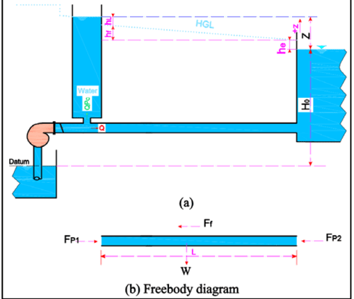
The Surge Tower is placed downstream of the pump, and the pump feeds the upper reservoir from the lower reservoir. We are interested in what happens at the head and volumetric flow rate at the head of the pump when the pump is suddenly closed.
The main governing equation is given as:
The change in head is calculated from:
- is the total head losses during the flow.
- is the gravitational constant, 9.81 m/s^2/
- is the diameter of the pipe, 0.4 m.
- is the cross-sectional area of the pipe.
- is the volumetric flow rate of the pump, initially it is 0.25 m^3/s.
- is the change in head from the steady-value, initially it is assumed to be 0.
- is the factor of the Surge tower, the value used is 0.02.
- is the cross-sectional area of the surge tower, area is 5 m^2.
- is the length of the pipe is 2000 meters.
The SIMULINK Model is given as:
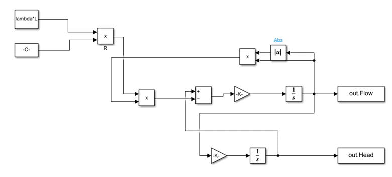
The results are shown below.
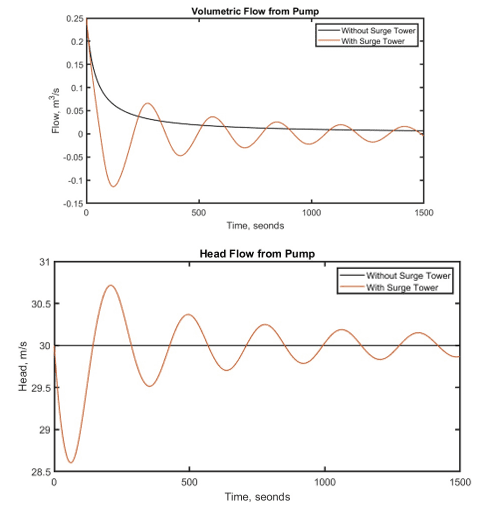
From the results, we see that if there is no surge tower, there is no change in head and it remains constant. For both the methods, the final steady-state value of head is 30 meters and the volumetric flow is set to 0 m^3/s since the pump is turned off.
What happens here is, with addition of Surge Tower, the flow of water is controlled inside the tower, and there are fluctuations in the main pipe, due to this, we see oscillations in the head and volumetric flow rate in the pipe.
Turbine Model Explanation
In the new model, we include water hummer effects as well. The whole model is taken from the paper that has been attached with the zip file. The schematics that represent the transfer function is shown below.
![]()
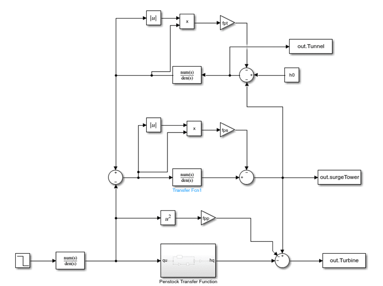
The block diagram is shown below.
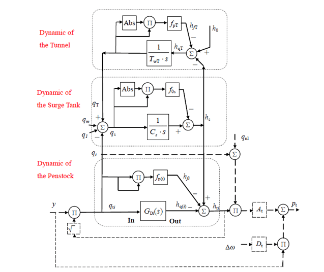
The above block diagram represents all three stages of the process. The input is supplied to the penstock, in which the demand is changed that is being supplied to the turbine. The change in demand affects the surge tower, and consequently, it affects the turbine.
The input to this model is given as:
Here, is the time constant of the motor used in penstock, and is step-input with . The remaining parameters are shown below.
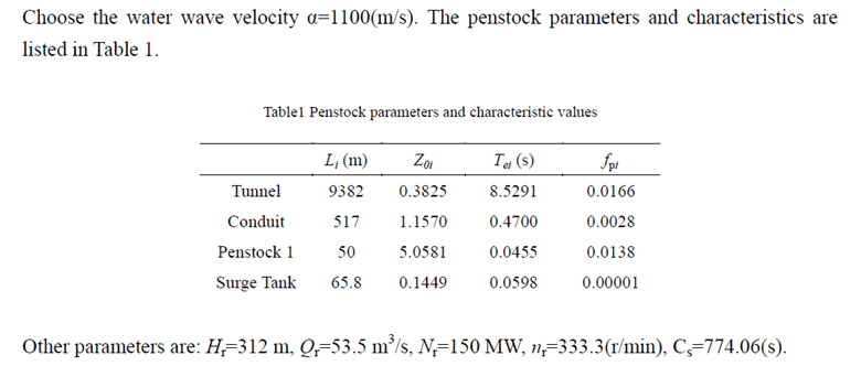
The results are shown below. The Simulink model is also shown below along with the MATLAB code.
The results below are shown without the surge tower for the head at the turbine.
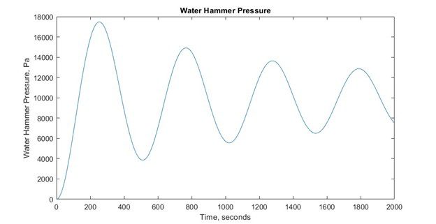
We can see a massive difference in the turbine head per unit with and without the surge tower. With the surge tower, we see that the head provided at turbine is far greater than without the surge tower.
% New Model Script
clc; clear; close all;
Hr = 312; % in meters
Qr = 53.5; % in m^3/s
Nr = 150e6; % in watts
nr = 333.3;
Cs = 774.06; % in seconds
alpha = 1100; % Wave velocity in m/s
h0 = 1;
% Tunnel Parameters
Lt = 9382; % in meters
Z0t = 0.3825; % Tunnel impedance
Dt = 8; % Tunnel diameter
fpt = Lt*0.014^2/((1/4*Dt)^(4/3))*(4*Qr/(pi*Dt^2))^2*1/Hr;
Tet = Lt / alpha;
% Conduit Parameters
Lc = 517;
Z0c = 1.1570;
Dc = 4.6;
fpc = Lc*0.014^2/((1/4*Dc)^(4/3))*(4*Qr/(pi*Dc^2))^2*1/Hr;
Tec = Lc / alpha;
% Penstock
Lp = 50;
Z0p = 5.0581;
Dp = 3.2;
fpp = Lp*0.014^2/((1/4*Dp)^(4/3))*(4*Qr/(pi*Dp^2))^2*1/Hr;
Tep = Lp / alpha;
% Surge Tank
Ls = 65.8;
Z0s = 0.1449;
Ds = 13;
fps = Ls*0.014^2/((1/4*Ds)^(4/3))*(4*Qr/(pi*Ds^2))^2*1/Hr;
Tes = Ls / alpha;
Ty = 20; % Time constant of servo motor
% Transfer function for penstock
num = [Tep^3 0 pi^2*Tep];
den = [4*Tep^2 0 pi^2];
[r,p,k] = residue(num,den);
% Create numerator and denomiator
num = conv(r(1),[1 -p(2)]) + conv(r(2),[1 -p(1)]);
den = conv([1 -p(1)],[1 -p(2)]);
k1 = k(1);
% Get all the data
D = sim(‘TurbineModel.slx’,2000);
t = D.tout;
surgeTower = D.surgeTower;
surgeTower = surgeTower*9804.14;
% Plot the results
figure
plot(t,D.Turbine)
xlabel(‘Time, seconds’)
ylabel(‘Turbine Head, meter’)
title(‘Turbine Head vs Time’)
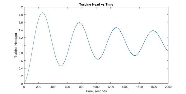
figure
plot(t,surgeTower)
xlabel(‘Time, seconds’)
ylabel(‘Water Hammer Pressure, Pa’)
title(‘Water Hammer Pressure’)