


Synthesis and Characterization of Potential Multiferroic Composites
Abstract
In recent years, a substantial amount of research is being conducted on multiferroic materials due to their profound physics and promising potential applications. These materials are being studied either in the form of single-phase multiferroic compounds or in the form of coupled composite systems. This project aims to synthesize a magnetoelectric multiferroic material with enhanced ME coupling and considerably good magnetic and electric properties. Ferromagnetic part of the composite system is cobalt ferrite and ferroelectric part is barium calcium zirconate titanate (BCZT). Two-stage solid-state reaction method has been employed to prepare single-phase and composite systems. Further, the magnetic and magnetostrictive properties of CFO have been altered through doping of In+3, Ga+3 and Al+3. On the other hand, the ferroelectric system (0.5) Ba (Zr0.2Ti0.8)O3 – (0.5) (Ba0.7Ca0.3)TiO3 (BCZT) is chosen based on literature review since it has very high piezoelectric coefficient (600 pC/N) and a good replacement for lead-containing multiferroic materials. Composite systems with the composition (0.2)CFO/CFXO–(0.8)BCZT (X = In+3, Ga+3 & Al+3) have been prepared. Mixed spinel structure of CFO and perovskite tetragonal structure of BCZT has been confirmed through X-ray diffraction (XRD) studies. XRD spectra of composite systems contain the diffraction peaks of both spinel and perovskite phases. All samples exhibited ferromagnetic character and CFO has the highest magnetization (87 emu/g). A high value of saturation magnetization is ascribed to the mixed spinel structure of CFO. The Al3+, In3+ and Ga3+ doped samples showed less magnetization as compared to pure CFO because of the non-magnetic nature of the dopants. The difference in magnetization values of In, Al and Ga doped samples despite similar concentration is attributed to the site preference on octahedral and tetrahedral sites. Moreover, saturation magnetization decreases with increase in temperature and is ascribed to the increased thermal energy which randomizes the magnetic moments. The increase in coercivity with a decrease in temperature is attributed to the increase in magnetic anisotropy at low temperatures. We believe that prepared composite systems will have high magnetoelectric coupling and satisfactory magnetic and electric properties. We believe that this system will have better magnetoelectric properties and will add a new degree of freedom in device functionality.
Chapter 1
1.1 Multiferroic Materials
Multiferroic materials have attracted much attention of the scientific community due to their significant properties in the 20th century and many new multiferroic materials have been discovered in recent few years [1]. Co-existence of two or more than two primary ferroic orders such as ferroelectricity, ferromagnetism and ferro-elasticity are known as multiferroics. The ferroic orders in these materials can be coupled which is known as Magnetoelectric (ME) coupling and it is the most interesting property of multiferroics which leads to the development of many electronic devices [2]. That is in ME multiferroics, magnetic properties can be altered through an electric field and vice versa. Control of magnetic fields through an electric field is more required for devices due to less power consumption [3].
Multiferroicity can be found in either single-phase or composite systems. In single-phase, two ferroic orders exist in one phase while composites can be made with enhanced ME effect by combining separate ferroelectric and ferromagnetic part [4]. There are various magnetically and electrically polarizable materials but few of them are ferromagnetic or ferroelectric as shown in Fig. 1.1. Multiferroics are rare in nature and magnetoelectric multiferroics are even rarer that is why people are trying to make more composite multiferroics by combining materials having different phases.
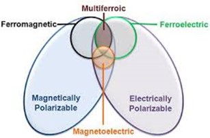
Figure 1.1 Overlap for a material to be classified as Multiferroics
In recent years, multiferroic materials have been very popular in the manufacturing of modern technology such as information storage devices, Spintronics, sensors, device miniaturization, actuators etc. [5][6].
1.2 Types of Magnetic materials
The word magnet is derived from the Greek term “magnētis lithos” meaning “the magnesian stone, lodestone”. Magnetism was first observed by Greeks in magnetite (Fe3O4), also known as Lodestone but they were not able to find the exact physics behind this at that time [7]. Magnetism arises due to spin and orbital motion of electrons. The material should have partially filled orbitals to show net magnetic moment. Magnetic behaviour of materials disappears above a certain temperature called Curie temperature (Tc) and it is different for different materials [8].
All substances possess magnetic properties but their response to an external magnetic field is different. These materials can be differentiated through their susceptibility which is,
χ = ——— (1.1)
Here, M is the degree of magnetization of material & H is applied magnetic field.
So, magnetic materials are classified in the following categories based on their response to the applied external magnetic field [9].
- Ferromagnetic materials
Ferromagnetic materials have a large positive value of susceptibility and show strong attraction in an external field. These materials have a spontaneous alignment of magnetic moments even in the absence of an external magnetic field that’s why they behave like a magnet. Ferromagnetic materials behave as paramagnetic above Curie temperature.
- Antiferromagnetic materials
These materials show strong repulsion in external field and susceptibility for such materials is zero. Magnetic moments are aligned in opposite direction with the same magnitude due to which they cancel each other out so these materials have no net magnetic moment.
- Ferrimagnetic materials
This is the subclass of antiferromagnetic materials because here, magnetic moments are also oppositely aligned but with different magnitude which is why these materials have a net value of the magnetic moment. Susceptibility is positive for such materials.
- Paramagnetic materials
These materials have a positive value of susceptibility and show attraction in the presence of an external field. They have a net value of the magnetic moment and these moments have random orientations in the absence of an external magnetic field but get aligned in the direction of the field when it is applied.
- Diamagnetic materials
Diamagnetic materials have a negative value of susceptibility and show repulsion in the presence of an external field. Due to paired electrons, the net magnetic moment is zero.
Alignment of magnetic dipoles for each type of magnetic material as explained above is shown in Fig. 1.2.
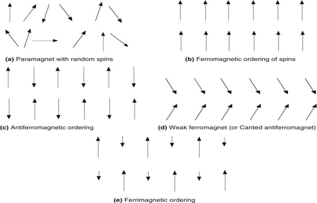
Figure 1.2 Ordering pattern of magnetic moments for different magnetic materials
1.3 Ferromagnetic materials response in an applied field
Ferromagnetism is the spontaneous alignment of spins in the same direction and that alignment can be changed by an applied external field. Exchange interactions are responsible for this alignment. These materials remain magnetized even when the external field is removed. Transition metals such as iron, cobalt, nickel, and alloys containing these materials and some rare earth metals are ferromagnetic. Hysteresis loop shows the behaviour of magnetization vs. field in these materials when applying external field on them Fig. 1.3. Ferromagnetic materials are either soft or hard magnetic materials depends on their coercivity. These materials are used in many technological devices such as transformers, wireless radio, speakers, television, radar and storage devices etc. [10]. Important parameters related to magnetic hysteresis loop are saturation magnetization and coercivity. Saturation magnetization is the point where all magnetic dipoles get aligned in the direction of applied field and coercivity is the required intensity of the magnetic field that can bring the material to its original demagnetized state.
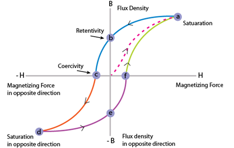
Figure 1.3 Hysteresis loop for a ferromagnetic material
1.4 Exchange interactions
It is the most important phenomenon in magnetism in which magnetic moments influence neighbouring magnetic moments and try to align them parallel or antiparallel. These interactions are a result of the overlapping of the wave function of individual particle and Coulomb interaction. This phenomenon is known as exchange interaction and is responsible for a material to be categorized as ferromagnetic or antiferromagnetic. In the case of ferromagnetic, magnetic moments are aligned parallel and in case of antiferromagnetic, magnetic moments are aligned antiparallel. Exchange interactions can be direct or indirect and are nothing more than the electrostatic interaction which occurs to minimize the energy of the system. If magnetic ions are directly overlapping, then this type of interaction is a direct exchange. And if magnetic ions are not overlapping directly and they need some nonmagnetic intermediate ion to interact, this type of interaction is known as an indirect exchange. Super exchange interactions and double exchange interactions are types of indirect exchange interaction. There are some other interactions such as RKKY interactions, anisotropic exchange interactions and Heisenberg exchange interactions. We will discuss superexchange interaction relevant to our study [11].
1.4.1 Superexchange interaction in cobalt ferrite
The interaction between the moments of magnetic ions which are far apart to couple directly, so they interact through some intermediate non-magnetic ion (Fig. 1.4) is explained by superexchange interaction represented as A-O-B. In cobalt ferrite, these interactions take place between Fe-O-Fe and Fe-O-Co. Magnetic moments for Fe-O-Fe are present with the same magnitude but opposite in direction on both tetrahedral and octahedral sites, so they cancel each other out. Interaction between Fe and Co is responsible for net magnetization in cobalt ferrite because they have magnetic moments of unequal magnitude.
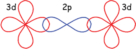
Figure 1.4 Schematic of superexchange interaction
1.4.2 Magnetic anisotropy
Magnetic anisotropy is the directional dependence of magnetization of a material. It is easy or hard to magnetize an anisotropic material depending on which direction an external field is applied. Anisotropic materials have easy and hard axes as shown in Fig. 1.5. Saturation magnetization can be easily achieved along the easy axis at a low external applied field. Magnetization along hard axes needs more energy. Spin-orbit coupling is responsible for magnetocrystalline anisotropy. The orbital moment is quenched in bulk samples due to the high crystal field, so the energy of the system depends on spin orientation and crystal axes. Anisotropy is small in highly symmetric structures such as cubic structure. Strains in a material introduce magnetoelastic anisotropy [12].
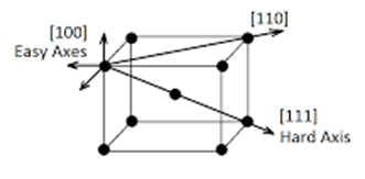
Figure 1.5: Anisotropic material with an easy and hard axis
1.5 Dielectric Materials
Dielectric materials are poor conductors of electricity. These materials have a high value of the energy bandgap and can be polarized by applying an external electric field. When a dielectric is placed in an external field, positive charges shift in the direction of the field and negative charges move in the opposite direction causing dielectric to polarize. Due to this separation of charges, an internal electric field generates in the opposite direction of the external electric field and reduces the overall field as shown in Fig. 1.6. There can be different types of polarization in a dielectric material depending on the formation and orientation f dipoles such as electronic, ionic, orientational and space charge polarization. Dielectric materials can be polar or non-polar. Polarizability of any dielectric can be determined through dielectric constant which is a ratio of the permittivity of material to the vacuum permittivity denoted as ɛr [13].
ɛr = (1.2)
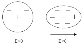
Figure 1.6: Separation of charges in a dielectric material
1.6 Ferroelectric materials
Ferroelectricity was discovered by Valasek in 1921. It is the spontaneous alignment of electric dipoles which can be switched by applying external field. These materials undergo phase transition above a certain temperature called Curie temperature. Perovskite structure ferroelectrics have great importance due to their industrial applications. Ferroelectric materials are used in ferroelectric capacitors, memory devices, ultrasound machines, sensors and also used as catalysts [14].
These materials exhibit the same hysteresis loop as ferromagnetic materials. Different parameters such as saturation polarization, remnant polarization and coercive field can be determined from the hysteresis loop shown in Fig. 1.7.
Figure 1.7: Hysteresis response of a ferroelectric material
1.6 Cobalt Ferrite; CoFe2O4 (CFO)
CFO is a hard magnetic material because it is chemically stable and mechanically hard. It has high coercivity, moderate saturation magnetization, high magnetostriction and high Curie temperature. Due to these exciting properties of CFO, it has been widely used in high-density information storage, microwave devices, sensors, as a catalyst, magnetic drug delivery etc. Structural, magnetic and electrical properties of CFO can be changed by introducing different ions in material, adapting different methodologies for synthesis, changing preparation conditions [15][16].
1.6.1 The crystalline structure
Like most of the ferrites, cobalt ferrite has spinel structure shown in Fig. 1.8 with a formula AB2O4, where A is a divalent cation such as Co+2, Mg+2, Mn+2 and B is a trivalent cation such as Fe+3, Al+3, In+3. Spinel structure was first reported for magnetite Fe3O4 and MgAl2O4 in 1915. These structures have cubic symmetry with a close-packed arrangement of oxygen ions and different distribution of divalent and trivalent cation on octahedral (O) and tetrahedral (T) sites. There are formula units in a cubic unit cell with 32 O and 16 T sites. Spinel structure is further categorized in the normal, inverse, and mixed spinel. In normal spinel, divalent cations A are present at the tetrahedral site and trivalent cations B are present at the octahedral site. The general formula for normal spinel is [A+2]T[B+3]OO4. In the case of inverse spinel, divalent cations A occupy the octahedral (O) site and trivalent cations B are present on both octahedral (O) and tetrahedral (T) sites. The general formula for inverse spinel is [B+3]T[A+2B+3]OO4. But if both divalent A and trivalent B cations are present on both octahedral (O) and tetrahedral (T) sites then the structure is mixed spinel with the general formula [Ax+2B1-x+3]T[A1-x+2B1-x+3]OO4. Cobalt ferrite (CFO) also has a mixed spinel structure. Magnetic moments of atoms A and B are aligned in opposite directions on O and T sites due to which they cancel out each other. But the difference in magnitude of moments causes materials to show magnetic behaviour. That is why the Co+3 is responsible for the magnetic behaviour of CFO.
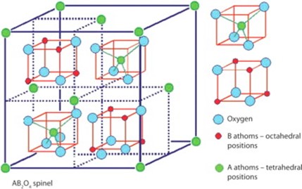
Figure 1.8: AB2O4 spinel structure
1.6.2 Literature review of Cobalt Ferrite
Cobalt ferrite (CoFe2O4) with its spinel structure represents the very important class of magnetic materials. It has unique properties such as good chemical stability, high magnetostriction and high saturation magnetization. The combined electrical and magnetic properties of cobalt ferrite make it very useful for technological applications. The properties of cobalt ferrite can be altered according to the desired application and it can be done by various methods such as different synthesis techniques, the substitution of different elements, heating conditions, particle size etc.
Nlebedim, I.C. et al. [17] reported the effect of heat treatment on the magnetic and magnetoelastic properties of cobalt ferrite. According to this research increase in temperature cause a decrease in magnetostriction, coercive field and anisotropy while an increase in magnetization. It all happens due to the redistribution of Co+2 and Fe+3 on tetrahedral and octahedral sites. Houshiar, M. et al. [18] synthesized the nanoparticles of cobalt ferrite using three different methods; combustion, co-precipitation and precipitation. It was observed that different synthesis techniques result in different particle size and magnetization. Magnetization decreases as particle size decreases, so magnetization was highest in combustion and lowest in precipitation method.
Kumar, R. et al. [19] studied the effects of In substitution on structural properties and cation distribution of cobalt ferrite. It was observed that at a lower concentration, indium ions prefer tetrahedral site due to which magnetization increases. At higher concentration, indium ions start moving towards the octahedral site which causes a decrease in magnetization. Song, S.H. et al. [20] reported magnetic and magnetoelastic properties of Ga substituted cobalt ferrite. It was noticed that Ga ions prefer tetrahedral site. Coercive field decreases with increase in Ga content which is why Ga doped cobalt ferrite shows softer magnetic behaviour. Zaki, H.M. et al. [21] reported the effect of Al doping on magnetic properties of cobalt ferrite. It was found that Al ions prefer octahedral site but at higher concentration, they start entering the tetrahedral site. Magnetization, coercivity and Curie temperature decreases within Al concentration. Magnetization also decreases with increase in temperature.
1.7 Barium Titanate (BTO)
Piezoelectricity was first discovered around the 1940s in Barium titanate. BCZT (Ca and Zr doped BaTiO3) is a ferroelectric material and has perovskite structure ABO3. It has a high piezoelectric coefficient (600 pC/N) and high dielectric constant. Its properties can be controlled by doping or varying the concentration of already present dopants. BCZT has become a very attractive material due to its environment-friendly nature as it is lead-free. It has a wide range of technological applications such as a capacitor, piezoelectric actuators, sensors etc. [22].
1.7.1 Crystalline structure
BCZT is calcium and zirconium doped barium titanate which has perovskite structure which exists in the form ABO3, where A is divalent cation and B is a tetravalent cation. These types of structures have cubic symmetry with A and oxygen atoms occupy corners and faces of cube respectively while B atom resides at the centre of the body. In a unit cell, three oxygen ions, one A and one B ions are present as shown in Fig. 1.9.
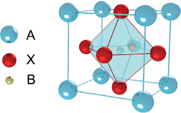
Figure 1.9: Cubic ABO3 perovskite unit cell with a = b ≠ c lattice parameters
1.7.2 Literature review of BCZT
BCZT is most widely used ferroelectric material due to the high value of the piezoelectric coefficient and its environment-friendly nature. Buatip, N. et al. [23] investigated the effect of sintering conditions on the electrical properties of BCZT. Grain size and density vary with sintering conditions. Maximum values of density, saturation polarization, the dielectric constant was observed for sample sintered at 1300 C for 4 hr. Jing Shi, et al. [24] reported the effect of rare-earth doping in BCZT. Highest saturation polarization was reported for Eu doped sample and best piezoelectric properties were observed in Yb doped sample.
Butnoi, P. et al. [25] reported the effect of BCZT as dopant on PZT ceramics. Value of dielectric constant first increased and then decreased with BCZT content. Curie temperature was observed to be decreased with the addition of BCZT. Wei Li, et al. [26] studied structural and dielectric properties for different concentrations of Ca. It was found that orthorhombic-tetragonal phase transition shifts towards lower temperature and dielectric constant decreases with an increase in Ca content.
1.8 Motivation
Multiferroic materials have attracted the scientists and engineers due to co-existence of ferroelectricity and ferromagnetism at room temperature and their technological applications. Multiferroics can exist in single-phase and composite form. However, single-phase multiferroics are rare and have weak magnetoelectrics coupling. On the other hand, composite multiferroics have strong ME coupling due to the freedom of choosing single phase magnetic and ferroelectric materials with exciting properties. We have worked on the synthesis and characterization of ferromagnetic single-phase cobalt ferrite (CFO), doped cobalt ferrite (CFXO; where X=In, Ga, Al) and ferroelectric single-phase barium calcium zirconium titanate (BCZT) and their composite systems (0.2)CFO-(0.8)BCZT and (0.2) CFXO-(0.8)BCZT (where X = In, Ga, Al). The goal of this research was to prepare a multiferroic material with high magnetoelectric coupling coefficient with good electric and magnetic properties.
Cobalt ferrite is a ferrimagnetic material with high magnetization and we doped it with In, Ga and Al to enhance its magnetostrictive and magnetic properties. On the other hand, we chose BCZT which is a good ferroelectric material. It has a very high piezoelectric coefficient of 600 pC/N, and it is a good replacement for lead-containing ferroelectrics.
The main goal of our research was to first enhance the properties of CFO through doping and then combine it with BCZT to achieve a good magnetoelectric coupling coefficient. To the best of our knowledge, there is no reported study on these systems with selected concentrations.
Chapter 2
Experimental & Analytical Methodology
In this chapter, the experimental method and different characterization techniques are explained which were used in this project to study the various properties such as structural, magnetic, and dielectric properties. Samples that were prepared include pure cobalt ferrite; CoFe2O4 (CFO), Indium, Gallium and Aluminium doped CFO; that is CoFe1.5X0.5O4 (CFXO) where X = In, Ga and Al, barium calcium zirconium titanate (0.5) Ba (Zr0.2Ti0.8) O3 – (0.5) (Ba0.7Ca0.3) TiO3 (BCZT) and their composite systems which are 0.2 CoFe2O4 – 0.8 BCZT (CFO-BCZT) and (0.2) CoFe1.5X0.5O4 – (0.8) BCZT (CFXO-BCZT) where again, X= In, Ga and Al. Synthesis of above-mentioned materials was conducted in magnetism lab and centre for micro and nano-devices CUI.
2.1 Synthesis
2.1.1 Solid-state reaction method
The solid-state reaction is the most used method and can be performed by just mixing/grinding of precursors in organic solvent i.e., acetone, then followed by heating them in the furnace below their melting point. Heat treatment is required for the reaction of mixed precursors and heating conditions are different for different materials depending on their melting points. Polycrystalline solids are obtained through this process without damaging them and this method is also not expensive.
In the solid-state reaction method, there are 2 steps to be followed:
- Weighing and mixing
The first step is done by weighing the precursors after calculating their stoichiometric amounts then mixing them in mortar and pestle in the presence of organic liquid (acetone) to make a homogeneous mixture.
- Heat treatment
In the second step, the homogeneous mixture was heated in the box furnace to make a polycrystalline solid. Two heat treatments are required to make a final material. Crucibles are used as containers to heat the samples because they can sustain high temperature. Heating time and temperature are dependent on the properties of the sample. Precursors are grinded again between the two heat treatments to make sure that mixture is homogeneous.
- Calcination is the first heat treatment in which materials are heated in the box furnace. This heat treatment is done in the limited supply of oxygen. Calcination is an endothermic process because system absorbs heat due to thermal decomposition. Samples are treated at a temperature below their melting point to remove volatile substances.
- Sintering is the second heat treatment in which materials are heated at sufficiently high temperature without reaching their melting point. Structure and chemical changes occur in this heating process. It improves the crystallinity of the sample and removes defects. Sintering is an exothermic process and affects the size and shape of particles. Fig. 2.1 shows the effect of sintering process on the sample.
Figure 2.1: Stages of the sintering process
2.2 Structural Analysis
2.2.1 X-ray Diffraction
X-ray diffraction is an important technique to characterize a material. It is used to obtain the structural information of crystalline materials. One can identify material and enable to find the impurities if exist any by using its XRD pattern. In XRD, when X-Ray beam hits the crystal, it gets diffracted through regularly spaced atoms of the crystal. Incident X-rays are scattered in different directions by atoms and the intensity of diffracted X-Rays can be measured by using diffractometer [27].
Diffractometer consists of 3 components: X-Ray tube, sample holder and detector and typically use Bragg-Brentano geometry to measure the intensity of diffracted X-Rays beam as a function of angle. The most used geometries are θ-θ or θ-2θ. In θ-θ geometry, the sample is fixed, and tube and detector rotate while in θ-2θ geometry, the tube is fixed and sample and detector rotate. Fig. 2.2 shows the Bragg-Brentano geometry.
Figure 2.2: Bragg-Brentano geometry
- ω is the angle between the incident beam and the sample.
- 2θ is the angle between the incident beam and the detector.
Lattice spacing (d) can be measured from Bragg’s law. Fig. 2.3 shows the schematic diagram of Bragg’s law and mathematically given by:
2dsinθ = nλ (2.1)
Here, d is lattice spacing, n is the order of diffraction, λ is the wavelength of X-Ray (1.54A°) and θ is the angle between the incident beam and the plane.
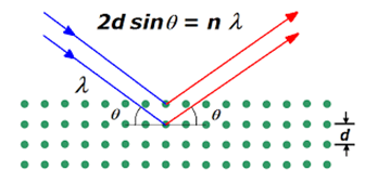
Figure 2.3: X-ray reflection from lattice planes showing Bragg’s law
2.2.2 Lattice constants
As mentioned earlier in chapter 1, CFO has a mixed spinel structure and BCZT has a perovskite structure. Both samples have cubic symmetry, so we used the following formulas to calculate the lattice parameters of these samples.
dhkl = (2.2)
a = lattice parameter
(h, k, l) = miller indices
d = spacing between angle and plane
d = (2.3)
And for unit cell volume
V = a3 (2.4)
2.3 Vibrating Sample Magnetometer (VSM)
Vibrating sample magnetometer is a scientific instrument used to measure the magnetic properties of a material. This instrument works on the principle of Faraday’s law according to which, change in a magnetic field produces an electric field.
Mathematically,
ε = (2.5)
Induced emf is directly proportional to the rate of change of magnetic flux
In VSM, the sample is placed between two electromagnets which produce a uniform magnetic field. This magnetic field aligns the domains of the magnetic sample and magnetizes it. Then the sample is vibrated at a frequency of about 85 Hz in the perpendicular direction to the external magnetic field. Due to the vibration, magnetic field of sample changes which causes a perturbation in the external magnetic field. Pick up coils that are arranged around the sample detect resulting emf due to changing magnetic field. This emf is then fed to the lock-in amplifier which picks up the signals only at the vibrating frequency. Through this procedure, we get magnetization of a sample [28][29]. Schematic diagram of VSM is shown in Fig. 2.4.
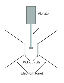
Figure 2.4: Schematic diagram showing Vibrating Sample Magnetometer
Chapter 3
Synthesis and Structural Characterization
3.1 Synthesis and structural study of Bulk Samples
In this chapter, the synthesis procedure and structural properties of prepared materials will be discussed. Two-stage solid-state reaction method was employed for the preparation of all samples. For the synthesis part, all details such as precursors and their stoichiometric amounts that were used in the preparation of sample are given. X-ray diffraction technique was used for phase confirmation and to obtain structural information such as lattice parameters, unit cell volume etc.
3.1.1 Synthesis Method
Solid-state reaction method which was used in the preparation of samples is described with the help of flow chart as shown below in Fig. 3.1.
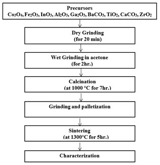
Figure 3.1: Flow chart showing steps for the preparation of bulk samples and composites
3.1.2 Precursors
Precursors that were used in the preparation of multiferroic composites are given below in table 3.1.
Table 3.1: Precursors used to prepare bulk samples
| Name | Chemical Formula | Purity Percentage |
| Cobalt Oxide | Co3O4 | 99.5 |
| Iron Oxide | Fe2O3 | 99 |
| Indium Oxide | InO3 | 99.5 |
| Aluminum Oxide | Al2O3 | 99.5 |
| Gallium Oxide | Ga2O3 | 99 |
| Barium Carbonate | BaCO3 | 99.9 |
| Titanium Oxide | TiO2 | 99.9 |
| Calcium Carbonate | CaCO3 | 99.9 |
| Zirconium Oxide | ZrO2 | 98 |
3.2 Synthesis of pure Barium Calcium Zirconium Titanate (0.5) Ba(Zr0.2Ti0.8)O3 – (0.5) (Ba0.7Ca0.3)TiO3 (BCZT)
Two-stage solid-state reaction method was used to synthesize single-phase ferroelectric part BCZT. To synthesize BCZT, following precursors which include Barium carbonate (BaCo3), Titanium oxide (TiO2), Zirconium oxide (ZrO2) and Calcium carbonate (CaCo3) were used.
We calculated the stoichiometric amount of these precursors using their molar masses after balancing the following chemical equations.
BaCo3 + 0.8TiO2 + 0.2ZrO2 BaZr0.2Ti0.8O3 + CO2 (3.1)
0.7BaCO3 + TiO2 + 0.3CaCO3 Ba0.7Ca0.3TiO3 + CO2 (3.2)
(0.5) Ba (Zr0.2Ti0.8) O3 – (0.5) (Ba0.7Ca0.3) TiO3 (3.3)
Calculated amounts of each precursor that was used to prepare BCZT is given in table 3.2 and table 3.3, respectively.
Table 3.2: Stoichiometric amounts of precursors used to prepare half part of BCZT, Ba(Zr0.2Ti0.8)O3
| BaCo3 | TiO2 | ZrO2 | Ba(Zr0.2Ti0.8)O3 |
| 9.664g | 3.1289g | 1.2069g | 13.99g |
Table 3.3: Stoichiometric amounts of precursors used to prepare the other half part of BCZT which is (Ba0.7Ca0.3)TiO3
| BaCo3 | TiO2 | CaCo3 | (Ba0.7Ca0.3)TiO3 |
| 7.797g | 4.508g | 1.694g | 14g |
3.2.1 Experimental procedure
In a typical procedure, calculated amounts of precursors were placed into Agate pestle and mortar. First dry grinding of the powder was done to obtain a single colour, and then an appropriate amount of acetone was added and continuously mixed 2 hours to obtain homogeneous samples. During this process of mixing and grinding acetone gradually evaporated. The homogenized powder was calcined 1300°C for 7 hr inside a box furnace in a ceramic crucible at the ramp rate of 5 ºC/min and then cooled with the same. The obtained material was reground in a mortar and pestle and regrinding process was carried out in the presence of acetone for approximately further 2 hr. After regrinding, pallets of the prepared samples were formed. Palletization is a process to convert powder into a compact form. For palletization, the powder was put in a circular disc-shaped having dia. of 8 and 13 mm and pressure of about 5*106 kg/m2 was applied through a hydraulic press. During palletization, the powder was mixed with 2 at% Polyvinyl Alcohol (PVA). PVA acts as a binding agent and it is an organic material which burnt out during sintering. The prepared pellets were then placed inside a box furnace for sintering at 1400°C for 7 hr at a ramp rate of 5 ºC/min and then cooling was done with the same rate. Sintering is usually done at higher temperatures than calcination to make dense polycrystal.
3.3 Synthesis of pure CoFe2O4 and CoFe1.5X0.5O4 (X: In, Ga, Al)
For the preparation of ferromagnetic CFO, CFIO, CFGO and CFAO samples, solid-state reaction method was employed. Precursors used to prepare ferromagnetic part include Cobalt oxide (Co3O4), iron oxide (Fe2O3), indium oxide (InO3), gallium oxide (Ga2O3) and aluminium oxide (Al2O3).
A stoichiometric amount of precursors were calculated using their molar masses after balancing the following chemical equations.
Co3O4 + 3Fe2O 3CoFe2O4 + 0.5O2 (3.4)
Co3O4 + 2.25Fe2O3 + 0.75X2O3 3CoFe1.5X0.5O4 + 0.5 O2 (3.5)
Where, X= Al, Ga and In
The calculated amounts of precursors for the preparation of CFO, CFIO, CFGO and CFAO are shown in table 3.4, table 3.5, table 3.6 and table 3.7 respectively:
Table 3.4: Stoichiometric amounts of precursors used for the preparation of CoFe2O4
| Co3O4 | Fe2O3 | CoFe2O4 |
| 1.417g | 2.818g | 4.23g |
Table 3.5: Stoichiometric amounts of precursors used for the preparation of CoFe1.5Ga0.5O4
| Co3O4 | Fe2O3 | Ga2O3 | CoFe1.5Ga0.5O4 |
| 1.554g | 2.318g | 0.907g | 4.779g |
Table 3.6: Stoichiometric amounts of precursors used for the preparation of CoFe1.5Al0.5O4
| Co3O4 | Fe2O3 | Al2O3 | CoFe1.5Al0.5O4 |
| 1.661g | 2.478g | 0.527g | 4.666g |
Table 3.7: Stoichiometric amounts of precursors used for the preparation of CoFe1.5In0.5O4
| Co3O4 | Fe2O3 | In2O3 | CoFe1.5In0.5O4 |
| 1.459g | 2.178g | 1.262g | 4.899g |
3.3.1 Experimental procedure
Precursors which are discussed in the previous section were mixed in stoichiometric amounts in mortar and pestle. Dry grinding was done for 20 min until we obtained a single colour and then wet grinding with acetone for 2 hr was performed. After that, homogeneously mixed samples were calcined at 1000°C in box furnace for 7 hr with a heating rate of 10°C/min and then cool at the same rate. Temperature for all samples was kept the same.
3.4 Synthesis of composite systems
To prepare composite systems, already prepared single-phase ferroelectric and ferromagnetic systems were combined using the solid-state reaction method. The ratio of the magnetic part was kept at 20% whereas the ferroelectric part was kept at 80%. That is, following compositions of composite systems were prepared:
- (0.2) CFO – (0.8) BCZT
- (0.2) CFIO – (0.8) BCZT
- (0.2) CFGO – (0.8) BCZT
- (0.2) CFAO – (0.8) BCZT
Amount of single-phase materials combined to prepare composite systems are given in table 3.8.
Table 3.8: Amount of single-phase materials to prepare composite systems
| Samples | Amount |
| CFO | 0.8g |
| CFIO | 0.8g |
| CFGO | 0.8g |
| CFAO | 0.8g |
| BCZT | 12.8g |
3.4.1 Experimental procedure
To prepare composite systems, above mentioned ratios (20% magnetic and 80% ferroelectric) of single-phase materials were mixed in mortar and pestle. Again, initially, dry grinding for 20 min and then wet grinding in acetone for 2h was performed. After obtaining the homogenous mixture, pellets of diameter 8mm were prepared using hydraulic press under a pressure of 350 bars. Polyvinyl alcohol (PVA) was used as a binder for pellets. Then pelletized samples were sintered at 1300 °C for 5h in box furnace with the heating and cooling rate of 10°C/min.
3.5 Structural Analysis by X-ray Diffraction
3.5.1 Structural analysis of CFO, CFIO, CFGO and CFAO
The XRD spectra of un-doped CoF2O4 (CFO) is shown in Fig. 3.2. The XRD pattern has been indexed according to the standard card of COFe2O4 (CFO) (JCPPS card No.00-003-0864). The CFO sample crystallized in the mixed spinal structure having space group Fd3m. Moreover, no diffraction peak corresponding to any impurity phase is present indicating that the prepared sample is phase pure.
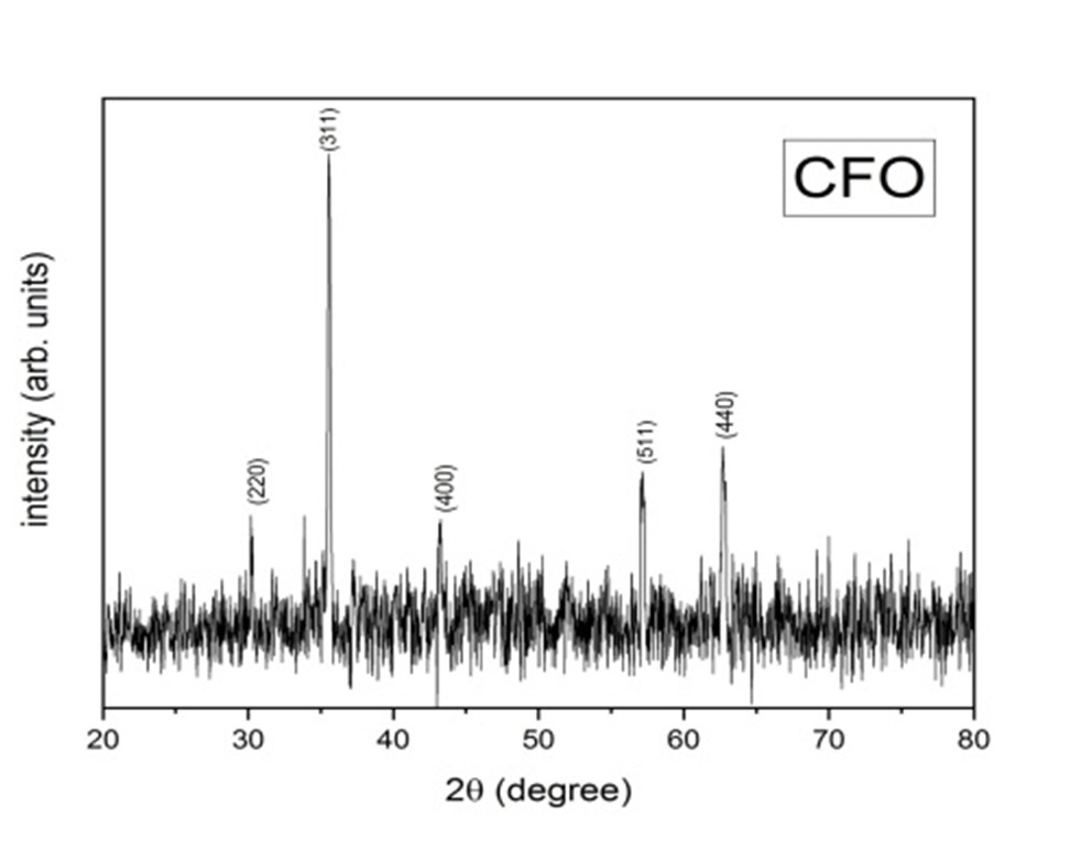
Figure 3.2: XRD result of CoFe2O4
The XRD spectra of In-, Ga- and Al-doped CFO samples is shown in Fig. 3.3 (a). All the doped samples also crystallized in the mixed spinel structure. A small amount of impurity phase is observed in In doped CFO sample, whereas all other samples are phase pure.
Moreover, it can be noticed that peaks of doped CFO samples are shifted towards higher or lower angle comparable to pure CFO. This shift in diffraction peaks can be explained considering the size difference between the host and the dopant. If ionic radii of dopant are smaller than the host, then unit cell volume decreases and peak shifts towards higher angle. Similarly, if ionic radii of dopant are greater than the host, unit cell volume increases and peak shifts towards lower angle. That is why the peak of Al (0.535pm) doped CFO is shifted towards a higher angle and In (0.80pm) doped CFO is shifted towards lower angle. Ionic radii of Ga (0.62pm) and Fe (0.645pm) are comparable due to which peak positions of Ga doped CFO are almost as same as of pure CFO. The ionic radii of Fe, In, Ga and Al are also given in table 3.9 below with coordination number and oxidation state:
However, there is a shift in peak positions of doped cobalt ferrite as compared to the pure cobalt ferrite which was observed in the XRD pattern. The difference in the XRD patterns of CFO, CFIO, CFGO and CFAO can be noticed in zoomed-in view of their XRD results in fig 3.3(b).
Table 3.9: Ionic radii of Fe, In, Ga and Al
| Name | Ionic Radii | Oxidation state | Coordination number |
| Iron | 0.645pm | +3 | IV |
| Aluminum | 0.535pm | +3 | VI |
| Gallium | 0.62pm | +3 | VI |
| Indium | 0.80pm | +3 | VI |
We have calculated the values of lattice parameters and unit cell volume with the help of XRD patterns using Bragg’s law for CFO, CFIO, CFGO, and CFAO samples which are given in table 3.10 below:
Table 3.10: Structural parameters of CFO and CFXO (X = In, Ga and Al)
| Parameters | CFO | CFIO | CFGO | CFAO |
| a | 8.3481 A° | 8.42290 A° | 8.37156 A° | 8.3481 A° |
| Volume | 581.93400 A°3 | 597.56469 A°3
|
586.69787 A°3
|
581.93400 A°3
|
3.5.2 Structural analysis of BCZT
The XRD spectrum of 0.5 Ba(Zr0.2Ti0.8)O3-0.5(Ba0.7Ca0.3)TiO3 (BCZT) sample is shown in Fig. 3.4. The perovskite tetragonal structure of BCZT was identified by XRD. However, along with the perovskite phase, small diffraction peaks of an impurity phase were also detected. The impurity phase is indicated by asterisk sign in the XRD graph and is identified to be Calcium titanate (CaTiO3). This impurity phase has been previously reported in the literature by Al3+ doping. The highest peak was observed at 2θ = 31.2758° which corresponds to the (110) plane.
Figure 3.4: XRD pattern of BCZT
Values of lattice parameter and unit cell volume are given in table 3.11 which were calculated with the help of XRD pattern by using Bragg’s law.
Table 3.11: Structural information of BCZT
| Parameters | BCZT |
| a | 3.99012 A° |
| Volume | 63.52693 A°3 |
3.6 Structural analysis of composite systems
XRD patterns of all four composite systems CFO-BCZT and CFXO-BCZT (where X = In Ga, Al) are shown in Fig 3.5(a), (b), (c) and (d). For comparison, along with the spectra of composite systems, XRD spectra for single-phase ferroelectric and ferromagnetic parts are also shown. As discussed before, each composite system was synthesized with the 20% ratio of ferromagnetic part and 80% of ferroelectric part. Therefore, it is expected that the diffraction peaks of the ferroelectric part will be more intense than the ferromagnetic part. We can note from figures that XRD pattern of composites contain diffraction peaks of both phases and ferroelectric part has more intense peaks in all composite samples as expected. The spinel cubic structure was observed for ferromagnetic samples whereas perovskite tetragonal structure of BCZT was identified by XRD. The impurity phase was found in the XRD pattern due to the presence of BCZT in the sample.
- (b)
- (d)
Figure 3.5: XRD patterns of all four composites along with their spectra of single-phase systems
Chapter 4
This chapter explains the detailed analysis of the magnetic properties of all prepared samples. These measurements were obtained using a vibrating sample magnetometer. Magnetic measurements were carried out as a function of magnetic field and temperature.
4.1 Magnetic Properties
This section is divided into three parts:
- Magnetic properties of cobalt ferrite CoFe2O4 (CFO) at room temperature.
- Magnetic properties of doped cobalt ferrite CoFe5X0.5O4 (CFXO; where X=In, Ga and Al) system at room temperature.
- Magnetic properties of CoFe5X0.5O4 (CFXO; where X=In, Ga and Al) at various temperatures.
Magnetic properties of single-phase systems
4.1.1 Magnetic properties of CoFe2O4 (CFO)
The magnetization as a function of the magnetic field (M-H) for cobalt ferrite is shown in Fig. 4.1. The magnetic measurements have been carried out up to a maximum applied field of 3T. Typical ferromagnetic hysteresis is obtained for CFO sample with a saturation magnetization of 87.34 emu/g. CFO is a hard magnetic material and it has a very high saturation magnetization varies between 60 to 80 emu/g depending upon the synthesis condition as reported in the literature [30]. This magnetic behaviour of CFO is mainly due to Co ions. CFO has mixed spinel structure with general formula AB2O4 having two sites; octahedral and tetrahedral. As CFO is a ferrimagnetic material and superexchange interactions are responsible for its magnetic behaviour. In case of an inverse spinel structure, half of the Fe3+ ions occupy tetrahedral site while the remaining half are present on octahedral site. Co2+ ions also occupy the octahedral site in the inverse spinel structure. Fe3+ (magnetic moment of Fe+3 is 5µB) ions on both sites are present in antiparallel alignment so they cancel each other effect. So the net magnetization is decided by the moment of Co2+ (magnetic moment of Co2+ ions is 3µB). That is,
Mnet = M B-site – M A-site (4.1)
In the case of the mixed spinel structure, both Co2+ and Fe3+ ions are present on tetrahedral and octahedral sites. That is some of the Co2+ ions from the octahedral site (B-site) are shifted to the tetrahedral site, which will result in a decrease in the magnetization of the tetrahedral site (A-site). This will increase the net magnetic moment which will increase magnetization. This happened in our case where we obtained a very large value of saturation magnetization for pure CFO (87 emu/g).
Figure 4.1: M-H loop of CoFe2O4 (CFO) at 300K
4.1.2 Magnetic properties ofCoFe1.5X0.5O4 (CFXO; where X = In, Ga and Al)
Figure 4.2 (a) shows the magnetic hysteresis curves for CoFe1.5X0.5O4 (CFXO; where X = In, Ga and Al) system. A slight decrease in the value of saturation magnetization (Ms) of doped samples is observed which is ascribed to the non-magnetic nature of In, Ga and Al. As dopant ions have no magnetic moment so their replacement with Fe+3 ions weakens the exchange interaction between the octahedral and tetrahedral site which causes a decrease in Ms value.
There is also a slight difference between the magnetization values of doped samples even after the concentration of all doped samples was kept the same. Al+3 doped CFO has the least value of saturation magnetization while Ga+3 doped CFO has a maximum value of saturation magnetization. The difference in values of saturation magnetization is due to the site preference of dopants. Al+3 ions have a strong preference for the octahedral site which results in decrease the moment of that site so net magnetization decreases. Ga+3 and In+3 ions prefer tetrahedral site due to which value of magnetization, in this case, is greater than that of Al+3 doped CFO. Also, the decrease in value of coercivity (Hc) has been observed in CFAO, CFGO and CFIO. Pure CFO saturates at the high magnetic field, but doped samples of CFO achieve their saturation magnetization at lower fields. These doped samples show softer magnetic behaviour due to the reduction in anisotropic energy. The decrease in coercivity is the indication of enhanced magnetostrictive properties [31][21]. The trend of Ms and Hc for CFO, CFAO, CFGO and CFIO are shown in Fig. 4.2 (b) and their values are given in table 4.1.
Table 4.1: Magnetic parameters of CFO, CFIO, CFGO and CFAO
| Sample | Ms (emu/g) | Hc (Oe) |
| CFO | 87. 34 | 582.92 |
| CFIO | 67.53 | 29.15 |
| CFGO | 74.73 | 46.47 |
| CFAO | 55.64 | 168.68 |
Figure 4.2(a): Hysteresis loops of CoFe1.5X0.5O4 (CFXO; where X=In, Ga and Al) at different temperatures
Figure 4.3(b): Trend of Ms and Hc for CoFe2O4 and CoFe1.5X0.5O4 (CFXO; where X=In, Ga and Al)
4.2 Magnetic properties of CoFe1.5X0.5O4 (CFXO; where X=In, Ga and Al) at various temperatures
Fig. 4.3 (a-d) shows the M-H loops of pure CFO, CFGO, CFIO, and CFAO at various temperatures between 5 K and 350 K with the difference of 50 K. Typical ferromagnetic hysteresis curves were obtained at all temperatures which imply that transition temperature lies below 350 K. The variation of saturation magnetization and magnetic coercivity as a function of temperature is shown in Fig. 4.3 (e-h). The saturation magnetization of pure CFO Fig. 4.3(a) increases with increase in temperature up to 150 K and then it starts decreasing with further increase in temperature. All other In3+, Al3+, and Ga3+ doped samples show a decrease in saturation magnetization with an increase in temperature. This is the typical behaviour of a ferromagnetic material below the transition temperature. That is, an increase in temperature will result in increased thermal energy which will try to randomize the magnetic moments. So, the exchange interaction between moments will weaken which will result in a decrease of magnetization. We can note that magnetic coercivity of the systems increases with decrease in temperature for all samples. An increase in coercivity with the decrease in temperature indicates an increase in magnetic anisotropy of all system.
Figure 4.4: Hysteresis loops of CoFe1.5X0.5O4 (CFXO; where X=In, Ga and Al) at different temperatures
Chapter 5 Conclusion
Multiferroic single-phase CoFe2O4 and CoFe1.5A0.5O4 (A = Al, In, and Ga) systems and their composites with BCZT have been developed by two-stage solid-state reaction method. The detailed structural and magnetic properties of single-phase and composite system have been studied. The X-ray diffraction studies revealed that pure CFO crystallized in a mixed spinel cubic structure. A shift in diffraction peaks toward higher and lower angles has been observed depending on the ionic size difference between dopant and the substituent which confirmed that dopants have been successfully introduced into the lattice. All samples exhibited ferromagnetic character and CFO has the highest magnetization (87 emu/g). A high value of saturation magnetization is ascribed to the mixed spinel structure of CFO. The Al3+, In3+ and Ga3+ doped samples showed less magnetization as compared to pure CFO because of the non-magnetic nature of the dopants. The difference in magnetization values of In, Al and Ga doped samples despite the same concentration is attributed to the site preference on octahedral and tetrahedral sites. The smaller magnetization value in case of Al-doped sample shows the preference of Al ions for octahedral sites which lowers the magnetization of this site. The higher value in case of Ga doped sample shows that these ions prefer to lie on tetrahedral sites which will lower the magnetization of this site. This will increase indifference of magnetization on two sites resulting in higher magnetization in case of Ga3+ ions. A decreased coercivity in case of the doped system indicates a decrease in magnetic anisotropy of the system. This decrease can be a signature of improved magnetostrictive properties as these systems are now more sensitive to an external magnetic field. BCZT on the other hand is a very good piezoelectric material. Thus, combining materials with high magnetostrictive and piezoelectric properties is expected to produce strong magnetoelectric coupling.