


Time-of-Flight Detection of Metal ions from Laser-Induced Plasma
Abstract
Powerful laser beams can create impressive effects of many kinds. In addition to vaporizing the material at the focal point, high-power laser pulses centered on a solid target often produce bright luminous plasma along with material ejection in various forms. Laser-induced plasmas are currently a topic of considerable interest in basic and applied scientific fields. Significant progress has been made in its application to many fields of basic research and material technology such as thin film deposition, cluster production, lithography, etching, annealing, and microelectronic devices manufacturing. The interaction between high-power laser beams and matter is a very complex phenomenon, resulting in several exotic processes. The time-of-flight ion analysis study of a laser-produced plasma is considered one of the most effective method for characterizing the laser-produced plasma
The work presented in this thesis covers the experimental results on the laser-produced plasma of several metals with a moderately high-power laser. The Time-of-flight technique (TOF) has been employed to measure the total ion flux through a Langmuir probe. The time of flight (ToF) signal of ions was collected by ablating Al, Cu, and W metals target by a Q-switched nanosecond Nd-YAG laser with a laser wavelength of 1064 nm and pulse duration of 20 ns. The ToF ion signal was investigated at different laser irradiances in the range of 4.58 x10⁸ Wcm-2 to 11.46 x10⁸ Wcm-2 to see the effect of laser irradiance on the properties of the ions. After investigating the ion signals it was seen that the ion yield was increasing by the increase in laser irradiance, however by increasing the atomic mass of the metal targets the ion yield tends to decrease. The results indicated the ion yield to be a function of the boiling point of the metal target by increasing the boiling point the ion yield was decreasing. The ion velocities were also calculated for all three metal targets and it was found to be inversely related to the atomic mass of the metal target i.e., lighter the particle higher the velocity it can gain. For the range of the laser irradiance mentioned above the most probable ion kinetic energies were also calculated. It was observed that the kinetic energy and ionization states of the ions of all three metals were increasing with the increase in laser irradiance. The calculated kinetic energies of Al and W ions were roughly the same, but the W ions were found to have a broader ion energy distribution as compared to Al and Cu.
1 Introduction
This chapter gives details about plasma, the characteristics of plasma behaviour, the classification of plasma, the reactions which take place inside the plasma and finally what is laser ablation, the different type of laser ablations and in-depth study of the process of photothermal ablation.
1.1 Plasma
Plasma is a mixture of ions, electrons, and neutral atoms, that collectively show certain properties. Figure 1.1 shows how plasma differs from ordinary gas. Because of the charge of plasma and the behaviour, it shows when it is subjected to the electric and magnetic field, which are not shown by other states of matter, plasma is considered the “fourth state of matter” after solid, liquid, and gas. In our daily life, we do not come into much contact with the state of plasma. As on earth most of the matter is in the form of solid, liquid, and gas. Hence the state of plasma is only found in a fluorescent tube or neon sign, in lightning storms and the aurora appearing in the polar region, on the surface of the earth because the low surface temperature and the high atmospheric density, that are essential for the existence of life forms, do not support the existence of the state of plasma. However, in the universe, all the stars including our sun, are a huge mass of high-temperature plasma. The nebula, the interstellar matter mostly consists of the state of plasma. Thus, 99% of all the matter found in the universe is in the state of plasma [1].

Figure 1.1 Plasma the fourth state of matter [2].
1.2 Characteristics of plasma
Nowadays there are many different methods through which plasma can be produced artificially in labs. However, in the 19th century when the state of plasma was first discovered in 1879 by William Crookes, plasma was only made by electrical charge methods [3]. This was done by making use of a sealed gas discharge tube which contained two metal electrodes, the pressure inside the tube was kept in the range of 10-1 to 1 torr and then a voltage was applied on the two metal electrodes. At low voltage, a small current flowed through the tube. However, when the voltage is increased to some hundred volts there is an abrupt change in the current flow through the tube and the tube then begins to glow. That indicates the formation of plasma inside the gas discharge tube. Hence, giving this method of generating plasma its name glow discharge plasma. What happens is that the very high voltage applied inside the tube ionizes the gas, (i.e creation of charged particles, ions, and electrons) which make the gas electrically conductive. The charged particles then move with random velocities in the opposite direction according to the applied electric field.

Figure 1.2 Glow discharge plasma [4].
Figure 1.2 displays what is called a Crookes tube, through which the state of plasma was discovered by Sir William Crookes. At that time he named it radiant matter, later on, it was given the name of plasma by Irving Langmuir in 1927 [5].
1.2.1 Plasma temperature
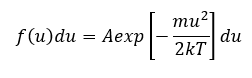
The random motion of the plasma particles, ions, electron, and neutral atoms can be characterized by the Maxwell distribution assuming that the system is in thermal equilibrium. The one-dimensional Maxwell distribution is denoted by,
| (1.1) |
where f(u) du is the number of particles per m3 with a velocity between u and u + du, k is the Boltzmann’s constant and ½ mu2 is the kinetic energy. The density of particles per m3 is specified by n which is,
 |
(1.2) |
where constant A is related to the density by,
 |
(1.3) |
The width of the distribution is described by the constant Temperature, and the average kinetic energy of the particle in the distribution is given by,
 |
(1.4) |
The 3-dimension average kinetic energy is given by,
In the plasma, the mean kinetic energy of ions, electrons, and neutral atoms are different, as compared to a system of gas particles, which have indistinguishable mean kinetic energy irrespective of the particle. Hence the temperature of the plasma is defined according to the temperature of the corresponding particles i.e. electron temperature Te, ion temperature Ti, and gas temperature Tg. Since each gas molecule has an internal energy structure of its own, the energy ϵ of the gas molecule is given by,
 |
(1.5) |
Here ϵtrans, ϵrot, ϵvib, and ϵelect are the energies corresponding to the translational, rotational, vibrational and electronic states, respectively. Also, the value of translational energy ϵtrans subtracted to the total energy ϵ is called the internal energy.
Once the system is at thermal equilibrium, then the distribution of internal energies of the particles in the system is given by the Boltzmann distribution law,
 |
(1.6) |
Here ni is the number of particles at the energy level ϵi, N is the total number of particles and gi is the statistical weight. Considering the case of molecules, the energies in them are due to the rotation, vibration, and electronic states. These energies are given by Trot rotational temperature, Tvib vibrational temperature, and Telect electronic temperature. In the case of electrons, the energy is only described by Te i.e. electron temperature since an electron has no internal structure like a molecule. The energy of plasma is given by several different temperatures. Which indicates that there is no thermal equilibrium among the particles of plasma. Generally, electrons and ions have separate Maxwellian distributions which are categorized by Te and Ti i.e. temperature of electrons and temperature of ions, respectively. However, the electrons and ions themselves may be at thermal equilibrium among themselves. This in response is due to the higher collision rate of electrons and ions among themselves instead of collisions between an electron and an ion.
1.2.2 Quasineutrality and Debye Shielding
We know that plasma is a mixture of ions, electrons, neutral atoms, and excited molecules. The ions and electrons have a positive and a negative charge on them, respectively. Thus, there must be some charge on the plasma. But it was found that plasma tends to be neutral in nature. However, the number of negative and positive charges per unit volume inside the plasma cannot be equal, because if this happens then there is going to be no electric field induced inside the plasma. Therefore, for the condition of the induced electric field to exist the charge densities of ions and electrons need to be different, such that a difference of one part per million between them causes the generation of an induced electric field inside the plasma. Nevertheless, this difference is so small that we can treat these densities to be equal. This is called macroscopic neutrality of plasma because macroscopically the plasma appears to be neutral or in other words “Quasineutrality” of plasma, which is a very important concept in plasma physics.
The condition for “Quasineutrality” is given by [6],
 |
(1.7) |
Here ni is the ion density and ne is the electron density.
There is a plasma criterion of “Quasineutral” which decides whether an ionized gas is to be called plasma or not. To evaluate the quasineutral concept a characteristic distance is introduced which is known as the Debye length λD. The quasineutral phenomenon requires that the dimension of plasma must be greater than the Debye length λD.
 |
(1.8) |
Also, Debye length necessitates that the number of particles inside a sphere of radius λD must be greater than unity [6],
 |
(1.9) |
Where ne is the number of electrons and λD is the Debye length
Plasma has an attribute that it shields itself from external fields, which is described as the Debye shielding. When a positively charged body is placed inside the plasma the electrons in the plasma almost instantaneously react to it by surrounding and forming an electron cloud over the positive charge. Whereas, in the case of an electron it repels other electrons in the surrounding and only positive charges remain hence a cloud of positive charges forms. The thickness of these clouds is given by Debye length λD [6],
| (1.10) |
Where k is the Boltzmann constant and T is the effective temperature of the particle.
The Debye length provides a distance in which an individual charged particle experiences an electric field. Beyond this length the electric field of the individual particle is negligible, and the collective effect of the particle is experienced. The concept of Debye length is a very important parameter for plasma studies.
If a charged matter is inserted it is surrounded by either ions or electron cloud (also called sheaths), depending on the charge on the matter inserted. These clouds shield the plasma from the electric field of the matter inserted inside the plasma. The Debye length gives us the thickness of the clouds in which the charge is shielded. Thus, outside the clouds or sheaths, macroscopic neutrality holds i.e. the quasineutrality, for the case of electron clouds as electron have much higher velocity than the ions because of their mass. They escape from the edge of the clouds because there is not a strong electric field present edge of the cloud and because of their very high velocities.
1.2.3 Plasma oscillations
| (1.11) |
Plasma oscillation is another very important concept in the field of plasma physics. One of the fastest and the most important collective motion is the bulk oscillation of plasma electrons around the ions. As in the plasma, the particle density distribution of ions and electrons is fluctuating. If at any point in space inside plasma the electron density increases than the background density subsequently the electrons are pulled back to their original position by the Coulomb forces applied by the ions. This keeps the plasma density distribution unvaried and the plasma charge to be neutral. But as the velocity of electrons in plasma is very high, due to which the electron will not remain at its equilibrium position it overruns it, after which again a coulomb force acts on it to keep the electron at its equilibrium position. This process is repeated every time the electron leaves its equilibrium position, to keep the plasma density distribution constant. As the electron oscillates back and forth across its equilibrium position, it oscillates with a frequency ωp called the plasma frequency. The plasma frequency depends on the density of electrons, charge, and mass of the electron and is given by the relation [7],
The collision between the ions and electrons damps these oscillations. And for the oscillations to be damped slightly, the collision frequency must be very small than that of the electron oscillation frequency,
| (1.12) |
Where ωp is the electron frequency and ωc is the collision frequency between the ions and electrons
Resonant-type phenomena with their characteristic frequency can also occur in plasma. For example, taking the case of ions oscillation, for ion oscillation we only need to change the mass of the electron in equation 1.11 with the mass of the ions and the equation then gives us the oscillation frequency corresponding to the ions.
If we introduce a magnetic field on the plasma, the charged particles, ions, and electron, then spiral around in response to the magnetic field with some characteristic frequencies which are called ions and electrons cyclotron frequencies, ωic and ωec respectively. The response of the plasma to the radiation incident on it is determined by these natural frequencies. If the frequency of the incoming wave matches one of the characteristic frequencies of plasma species, then a resonance interaction occurs and the energy transfer of the electromagnetic wave to the plasma is greatly enhanced. The relation for an electromagnetic wave travelling through the plasma is given by,
| (1.13) |
where ωp is the plasma frequency and c is the speed of light.
For the case of laser produce plasma there exist an electron density gradient then, ωp varies according to above electron frequency equation for ωp<ωi, k is real, and the wave propagates, for ωp>ωi, k is imaginary, and the wave is not transmitted. There is a condition called the critical density of plasma nc at which all the incoming wave is reflected, the condition of critical density appears when ωp = ωi, and is given by,
| (1.14) |
There is a very well-known example of reflection of the electromagnetic wave from the ionosphere of the earth, due to which long-range radio communication is possible. The ionosphere around the earth is a very dilute plasma and because of this, it can only reflect the radio frequency. As per the case of a very dense plasma, it can reflect the optical frequency range. Which proves to be a considerable important factor in laser-produced plasmas.
1.3 Classification of plasma
There exist different kinds of plasmas in nature along with plasmas which are created artificially in labs. Figure 1.3 shows the different classifications of plasma-based upon the plasma temperature. Plasmas are differentiated based upon their electron energy kTe and electron density. Broadly plasmas are classified into two groups thermal plasma and cold plasma.
1.3.1 Cold plasma
A plasma is termed as cold plasma if the particles inside the plasma are not in thermal equilibrium i.e. the electrons are at relatively at high temperature while the ions and neutral particles due to their low energies remain at low temperatures [8]. Cold plasmas can be generated using a discharge tube or microwave discharge, at low pressure. Plasma generated in the discharge tube under low-pressure condition have high electron temperature, however, the ions and electrons remain at relatively low temperatures as a result of the low pressure inside the tube, the frequency of electron and gas-particle collision is very low, due to which there is no thermal equilibrium between them. Cold plasma is also termed as “non-equilibrium plasma” due to the before-mentioned fact. The degree of ionization in cold plasma is below 10-4, hence the plasma mostly consists of neutral species.
| (1.15) |
The relative temperature of the cold plasma is given as,
1.3.2 Thermal plasma
| (1.16) |
In thermal plasma, the electron temperature and the gas particles temperature are approximately the same, due to the high collision frequency between the electron and the gas particles. Thermal plasma is also called “equilibrium plasma” because of the thermal equilibrium between the electrons and the gas particles. The condition of thermal plasma is given by,
Where Te is the temperature of electrons, and Tgas is the temperature of the gas particles.
At thermal equilibrium, the density of the particles is given as a function of temperature and pressure, on condition that the following reaction is at equilibrium,
| (1.17) |
where ui is the ionization potential of gas molecule A.
| (1.18) |
The degree of ionization α can be defined as,
| (1.19) |
Where nA is the number of neutral particles and nA+ is the number of charged particles.
The relation between α, temperature T, and pressure P is given using internal partition function QA and QA+ for A and A+, respectively
Where me is mass of the electron, h is the Plank constant. Equation 1.19 which is applied to the ionization of a neutral molecule A to a singly charged ion A+ is known as the Saha equation [9].

Figure 1.3 Classification of plasma depending on temperature and plasma density [7].
1.4 Plasma reactions
The plasma is a mixture of ions, electrons, neutral species, and excited atoms electron being the lightest species in plasma, can be excited easily by collisions with other excited electrons hence creating excited electron clouds, subsequently, these excited electrons clouds collide with other plasma species resulting in exciting other plasma specie. If the gain in energy is equal to or greater than the ionization potential, then the ion or atom ionizes, producing more excited electrons. These excited electrons and ions give rise to different kinds of reactions inside the plasma.
1.4.1 Collision phenomena
As mentioned, plasma contains charged particles and neutral species that are continuously colliding with each other. In these collisions, two types of collisions take place elastic collision and inelastic collision. Those collisions after which there is no change in internal energy of the particle is called an elastic collision. Whereas, collision after which there is a change in internal energy of the particles is termed an inelastic collision. Consider a particle with mass m and kinetic energy Ei which collides with a particle with mass M which is at rest. After the collision, the transfer of energy is given by,
| (1.20) |
The internal energy increase of a particle after an inelastic collision is given by
| (1.21) |
For the collision of electrons with neutral particles, the Et/Ei ratio is 0.01% and ΔU/ Ei is about 99%. However, the kinetic energy transfer of collision between neutral particles and electrons is very small.
Due to inelastic collisions, different reactions arise between the particles, such as excitation, ionization, and dissociation of gas particles. The excitation process includes different types of excitation such as between energy level, electronic excitation, vibrational excitation, and rotational excitation. The reaction cross-section for these reactions can be calculated and the total cross-section is expressed as the sum of all the reaction cross-sections
| (1.22) |
In the case of electron-electron collision, they do not result in any radiations except at very high velocities i.e. relativistic velocities. In plasma, the important collisions are those of which take place between the electrons and ions, and frequent, but inefficient collisions between electrons and neutral atoms.
1.4.2 Excitation and ionization
The following excitation and ionization processes of the plasma species are known
- Excitation and ionization by an electron collision.
- Excitation and ionization by an ion collision.
- Excitation and ionization by a neutral particle collision.
- Excitation and ionization by radiation.
The probability that one of the above reactions may occur is given by the cross-section of reaction.
An inelastic collision between an electron and an ion or neutral specie, which results in the conversion of the electron kinetic energy into excitation energy in the ion or neutral specie is called collisional excitation. Another process that takes place in these collisions is collisional de-excitation, which is the inverse process of collision excitation. In this, the excitation energy of the ion or neutral specie is converted to the kinetic energy of the electron. Electron because of their large mean velocity and long interaction range, can lead the two processes of collisional excitation and collisional de-excitation.
Collisional ionization takes place when the kinetic energy of the electron is equal to or greater than the ionization potential of an ion or a neutral. After which when the excited electron collides with the ion or neutral atom an electron is removed.
Collisional recombination is a process that occurs when an electron collides with an ion and recombines with the ion resulting in a gain in the kinetic energy of the atomic system.
The thermal ionization process takes place when the temperature of a gas is increased to a point such that the neutral atoms inside the gas get highly excited, as a result when they collide with another neutral atom or ion, they ionize the neutral atom or further increase the ionization degree of an ion. This type of ionization is caused due to the thermal excitation of the neutral particle hence termed as thermal ionization. This ionization is observed in arc plasmas or burning flames where the gas temperature is in several thousand degrees [10].
Penning ionization is the ionization process that takes place when an excited metastable particle and a neutral particle whose ionization energy is less than the excitation energy of the metastable particle collide. This results in the ionization of the neutral particle. The equation of the reaction is given as,
| (1.23) |
B* is the excited particle, A is the neutral particle and A+ is the ionized particle, e is the ionized electron. Penning ionization is significant in longer mean free-path pressure regimes.
Photoexcitation corresponds to the process in which an atom absorbs a photon and gets raised to a higher energy state or an excited state. The converse of this process is photodeexcitation or in other words emission process. In which when the atom emits a photon after dropping to a lower energy state.
Photoionization occurs when the incident photon has an energy which is equal to the energy difference between the lower and the higher energy level. This photon, when absorbed by the atom, ejects an electron from the atom and the atom is ionized. If the photon has energy greater than the ionization energy, then the difference between the photon energy and the ionization energy of the atom appears as the kinetic energy of the ejected electron. The photoionization cross-section is about an order of magnitude smaller than the cross-section of collisional ionization
1.5 Laser matter interactions
The laser, as a source of ‘pure’ energy in the form of monochromatic and coherent photons, is enjoying ever-increasing popularity. Because of its wide applications such as nuclear fusion reactors [11], ion accelerator [12], pulsed laser deposition [13], micromachining [14], and a newly discovered application of lasers to create nanoparticles of various materials [15].
Since the discovery of the ruby laser in 1960 many scientists around the world shifted their focus on the effects and the processes that take place when a high-powered laser is focused on a material [16]. The most studied and researched topic at that time was the theoretical model of the phenomena involved in the laser-matter interaction. Many experiments were performed by different scientists to check the validity of their models and later these experiments became the basis of many practical applications of laser-matter interaction. Although most of the phenomena of the laser-matter interaction were understood by the time of 1975, throughout time important refinements and insight have been made to these models and are still being made by the researchers for better understanding of the phenomena involved in laser-matter interactions.
The ability to manipulate the properties of laser-produced plasma (LPP) and ions emitted from the laser-produced plasma (LPP) must be accomplished to make the current application of laser-produced plasma (LPP) more advance and efficient, and for discovering new application of LPP.
1.5.1 Laser ablation
Laser ablation is the process in which material is removed from the surface of a target by irradiating it with a laser pulse. The removal of material depends on the wavelength of the laser, the intensity of the laser, and the spot size of the laser pulse [17].
When the radiation from a Q-switched nanosecond laser with adequate energy is incident on a target. One of the following mechanisms can take place on the target surface, photothermal ablation, photochemical ablation, and photophysical ablation [18]. Photothermal and photochemical ablations are set apart by the mechanism of laser radiation absorption by the material. While in photophysical ablation both the photothermal and photochemical ablation process take place to ablate a material.
In photothermal ablation, the laser energy is absorbed by the free electrons in the target. Which increases the energy of the electrons. That is then transferred to the lattice through the electron-lattice coupling. In metals targets, the electron-lattice coupling has a time constant in the order of picosecond (10-12 s) [19]. In the case of a nanosecond laser pulse, the pulse duration is much, longer than the electron-lattice coupling time constant. Therefore, the nanosecond laser pulse incident on the target material acts as a heat source for the target material. Due to which, there is a rise in temperature on the surface of the target material where the laser is incident, this rise in temperature results in surface melting and afterwards vaporization of the material. The initial temperature of the vapour formed over the material is related to the vaporization temperature of the ablated material. So, for the case of the nanosecond laser pulse and material which have initial free electrons (i.e. for the case of metals), the photothermal ablation can be used to explain the ablation in these materials. For dielectrics, polymers, and other types of materials, additional mechanisms are required to create initial free electrons such as multiphoton ionization, ionization from default levels, etc.
The photochemical ablation process takes place when the photon energy of the laser in high (i.e. at shorter wavelength), or the efficiency of multiphoton ionization is high. This results in enough energy being provided to the atoms as a result direct bond-breaking takes place in the volume of material where the laser is incident. Photochemical ablation takes place without any change in temperature in the material [20]. Due to bond breaking, there is very high mechanical stress buildup in the volume of material where the laser is incident upon, and this stress buildup results in the removal of material in the form of fragments. The photochemical ablation process describes the ablation process of dielectric and polymeric materials. Laser pulses in the Ultraviolet region are efficient to induce photochemical ablation.
When ablation takes place due to both photothermal and photochemical processes in material then it is said to be photophysical ablation process. In this ablation process initially, the photochemical process creates free electrons in the target material, after which the photothermal process efficiently provides energy to the free electron. The electrons then transfer this energy to the lattice through the electron-lattice coupling, which leads to the rise in temperature on the spot, afterwards the vaporization of the material from the spot where the laser is incident. The photothermal process is a combination of the thermal and non-thermal ablation process. This process best illustrates the ablation process in semiconductors and dielectric materials through nanosecond laser. High-temperature plasma can be generated from materials through the photophysical ablation process.
However, this thesis is on the study of ion emitted from a metal target. In metal, the ablation process is best explained by the photothermal ablation process because of the existence of abundant free electrons. So, we are going to focus on the phenomena involved in photothermal ablation processes.
1.5.2 Photothermal ablation
| (1.24) |
The photothermal process strongly depends on the absorption of a photon by the free electron in metals. The optical absorption properties of the material can be described by the absorption coefficient α. A laser incident on the material surface with irradiance Io, after travelling some path length in the material the laser becomes Il. This optical transmission is best described by the beer lambert law [21],
Where Rs is surface reflectivity, α is the absorption coefficient.
If we assume that all the light energy is absorbed by the material and converted into heat energy. We take the example of copper with the absorption coefficient α= 7.44 x10⁷. If we know the absorption coefficient, we can calculate the penetration depth as the absorption coefficient and penetration depth are inversely related (P = 1/α). So, penetration depth comes to be around 13 nm. As the penetration depth is much smaller than the spot size so we can consider that there is no lateral heat flow, there is only heat flow in the z-direction, the heat flow can then be described by a one-dimensional heat equation.[21]
| (1.25) |
In the above equation, the right-hand side first term describes the heat conduction, the second term indicates the energy coming from the laser energy absorption. T represents the temperature in the target, U describes the additional energy per unit volume and time that is required or provided if phase transition occurs, z is the distance measured from the target surface, t is the time, k, Cp and ρ denote the thermal conductivity, heat capacity and mass density of the target material respectively.
1.5.3 Explosive boiling (Phase explosion)
At low laser irradiances, the rise in temperature as a result of laser absorption by the metal is slow, hence the metal undergoes a normal heating process i.e. the temperature of the liquid metal is below the boiling temperature. On the other hand, if the intensity of the laser is high there is a sudden rise in temperature on the spot where the laser is incident, the temperature on the spot exceeds the boiling temperature. Due to which the liquid metal goes into a supercritical state, afterwards explosive boiling. Figure 1.4 is a pressure-temperature graph to explains the process phase explosion.
| [Grab your reader’s attention with a great quote from the document or use this space to emphasize a key point. To place this text box anywhere on the page, just drag it.] |

Figure 1.4 P-T graph for explosive boiling [22].
During the normal heating process, the temperature of the liquid metal is below the boiling temperature. As a result, there is an equilibrium between the surface temperature and the vapour saturation pressure which is shown by the binode line in figure 1.4.
However, at high powered laser heating, the liquid metal is heated to temperatures well above the boiling point while the surface vapour pressure does not build up rapidly. The liquid metal then becomes superheated, (i.e., its temperature is higher than the vaporization temperature) consequently the liquid becomes metastable. In this case, the heating process follows a superheating line shown in figure 1.4.
During high powered laser heating, the number of nuclei generated by spontaneous nucleation is negligible at temperatures lower than 0.9Tc. As the temperature reaches 0.9Tc (Tc=thermodynamic critical point) a significant number of nuclei form and the target material experiences an abrupt change in phase and the liquid metal turns into a mixture of vapour and liquid droplets. As close to the critical temperature there is no difference between the liquid and gas phase, they both coexist with each other. Afterwards, the vapour bubble starts to grow over the liquid metal and as the vapour bubble reaches a critical radius the bubble explodes ejecting a mixture of vapour and liquid droplets from the surface of the metal. This process is known as the phase explosion or explosive boiling. The time it takes for the vapour bubble to reach a critical radius is called the time lag of nucleation [22]. The time lag is an important concept in ablation induced by nanosecond laser pulses. The time lag of metals is estimated between 1 and 10 ns [23].
1.5.4 Plasma shielding
Another concept of plasma formation is plasma shielding, this phenomenon occurs at relatively high laser energy. As at high laser intensity the material ablation rate is very high, because of which the plasma formed above the material gets denser with time. In the case of the nanosecond laser pulse, the plasma is formed in the initial few nanoseconds after which the pulse interacts with the plasma for the remaining pulse duration. Subsequently, heating the plasma plume and the target material thereby increasing the amount of ablated material. The plasma produced by high laser energy quickly reaches a critical density, therefore, most of the laser pulse is absorbed by the plasma plume, consequently decreasing the amount of laser pulse delivered to the target material [24].

Figure 1.5 Effect on laser temporal profile by plasma shielding [25].
Figure 1.5 illustrates the effect of plasma shielding on the temporal profile of the laser pulse as we can see that by increasing laser energy the time for which the laser pulse deposits energy on the metal also becomes less because of the shielding effect [25].
1.5.5 Pre-ablation process
The process of ablation begins when a high-power pulsed laser is focused on a metal target. When the laser pulse interacts with the metal target different thermal excitation processes take place i.e. multiphoton ionization to create initial free electron in the metal, inverse bremsstrahlung to provide energy to the free electrons, followed by thermalization i.e. the electron transfer their energy to other electrons and the lattice atoms by inelastic collisions [15]. The time scale in which thermalization takes place is in the order of picoseconds (10-12 s) [19]. For the case of nanosecond (ns) laser, the pulse duration is longer than the thermalization time. Hence in the initial few nanoseconds of the laser interaction with the metal, the thermalization process starts to take place on the spot where the laser is focused. As a result, there is a rise in temperature on the spot. After some nanoseconds into the laser interaction with the metal, due to the thermal processes, the surface temperature (Ts) of the spot quickly reaches well above the boiling temperature of the metal (Tm). Consequently, the metals turn into a superheated metastable liquid which undergoes the process of explosive boiling (explain above), which turns the superheated liquid into a mixture of gas (i.e. plasma) and liquid droplets. The process mentioned here is for the case of the laser energy being comparable or greater than the ablation threshold (minimum amount of energy which is required to ablate a material is known as ablation threshold) of the material. For the case of laser energy lower than the ablation threshold no material is ablated, only the process of laser heating takes place.
1.5.6 Post-ablation process
As in the case of ns laser, plasma is produced during the initial few nanoseconds of the pulse, hence the remaining pulse now interacts with the plasma as well as the metal target. The interaction of laser pulse with the plasma is known as plasma heating, during which the electrons inside the plasma absorb a small part of the incoming laser pulse through inverse bremsstrahlung which increases their kinetic energy, therefore, the increase in electron-ions collisions consequently creating more ionization states inside the plasm. Whereas the interaction of the laser pulse with the metal prompts in more material ablation. For the case of very high-powered laser, the process of plasma shielding takes place which is explained above.
The plasma heating and plasma expansion process are explained by the electrostatic model, the energy transfer to the electrons in plasma heating (discussed before) is through IB, the process in which a free electron absorbs a photon whenever it passes by a neutral atom or an ion. The inverse bremsstrahlung absorption coefficient is given by.
| (1.26) |
Where ne is the electron density in cm-3, Te is the electron temperature in eV, IB in cm-1. Equation 1.26 gives us the relation of wavelength with the absorption coefficient of inverse bremsstrahlung (IB). By increasing the wavelength, the absorption coefficient value increases, and by decreasing wavelength the absorption coefficient value decreases. Due to this increase and decrease in the value of the absorption coefficient of inverse bremsstrahlung, there will a change in the kinetic energy of electrons. As mentioned above the electrons gain energy from the inverse bremsstrahlung process after which the collisions of the electrons with the other plasma species increase, consequently increasing their kinetic energy [26]. Therefore, at higher wavelengths the electrons will gain more energy from the inverse bremsstrahlung process, because of the more energy gain, electrons collision frequency with other plasma specie will be high, hence more energy transfer between the electrons and the plasma specie. While at low laser wavelength electrons will gain less energy from inverse bremsstrahlung consequently resulting in low collision frequency, because of which less energy will be transferred through collisions to the other plasma species [27].
Because the mass of the electron being much smaller than the mass of ions and neutral atoms, the electrons gain high velocities after the excitation process and escape the plasma plume leaving behind a deficiency of electrons. The electrons escape in the direction normal to the target material because of the pressure gradient which is created as a result of more material being removed from the target surface. From figure 1.6 the space charge separation can be seen between the high-velocity electrons that are trying to escape the plasma and the ions that lag due to their masses prevent the electrons from completely escaping the plasma, therefore the electrons are confined at the leading edge of the plasma plume. The separation between the high-velocity electrons and the dormant ions induce a self-electrostatic field between the ions and the electrons. This electrostatic field now start to accelerate the ions in the forward direction, as plasma is produced during the initial nanoseconds of the laser pulse, and the remaining pulse is still coming from the laser, therefore the electrons at the leading edge of the plasma plume are continuously gaining energy from the laser pulse through inverse bremsstrahlung absorption hence the process of ions acceleration is sustained through the induced electrostatic field. Consequently, the ions gain energies up to keV.

Figure 1.6 Space charge separation [19].
2 Experimental setup
In this Chapter the details of the experimental setup used for the time of flight measurement of the ions from the plasma generated through pulse laser ablation. The various system like laser system, ion collector, vacuum chamber, vacuum pump, vacuum gauge and digital oscilloscope used for the current experimental studies are discussed along with their features in this chapter.
2.1 Laser system
A laser is a device that emits a beam of light that has properties of being highly directional, intense, monochromatic, and coherent. The word laser is an acronym of “Light Amplification by Stimulated Emission of Radiation”.
The laser works on the principle of stimulated emission. The concept of stimulated emission was first given by Einstein in 1917. Stimulated emission is a process in which when a photon of a specific frequency interacts with an excited electron it causes the electron to de-excite and drops to a low energy level when the electron drops to the low energy level it emits a photon as seen in figure 2.1 [28]. The emitted photon and the incident photon have identical properties, such as the same energy, frequency, direction, and polarization.
Figure 2.1 Absorption and stimulated emission.
The photon emitted in this process has the energy which is equal to the energy difference between the two-energy level, it is given by the equation 2.1
| (2.1) |
h is the Plank constant here, E2 is the upper energy level and E1 is the lower energy level
For the process of stimulated emission to take place firstly an electron is excited to an upper energy level with the help of a photon that has the energy equal to the energy difference between the two-energy level, this process of excitation of an electron by a photon is called absorption.
If the excited electron de-excites to a lower energy level after some time without the influence of another photon this process is called spontaneous emission. A point to remember in both of these processes is that photon is emitted in both spontaneous and stimulated emission but in spontaneous emission the photon emitted is not directional neither it has the same phase as other photons emitted rather than the case of stimulated emission in which both the photons have same properties. A laser system takes advantage of absorption, spontaneous and stimulated emission
| (2.2) |
The frequency of the emitted photon is calculated by equation 2.2,
| (2.3) |
For the phenomena of laser to take place in a material, the condition of population inversion (N2>>N1) is needed to be fulfilled in a two-level system i.e. the population of electrons in the higher energy level must be greater than the population of electrons at the lower energy level. This may sound like an easy condition to fulfil, but rather it is not easy for the case of a two-level system. Because of spontaneous emissions that are continuously taking place in a two-level system and a large amount of electron availability at the ground state level of an atom, it is impossible to achieve the condition of population inversion (N2>>N1) in the case of a two-level system.
Suppose we have a material in which consists of a two-level system if all the atoms inside the material are in thermal equilibrium then the number of atoms that are at the ground state level and excited state level can be given by Maxwell Boltzmann relation as shown in equation 2.3,
Where k is the Boltzmann constant, T is the thermodynamic temperature of all the atoms, E1 is the energy of lower level, E2 is the energy of the upper level.
Equation 2.3 tells us that if we supply the atoms with infinite energy, we cannot achieve the condition of population inversion (N2>>N1) only the condition of N2=N1 is possible in this case, so even at very high temperatures, the population inversion is not possible in a two-level system.
Hence, we need to design a system in which the phenomenon of population inversion (N2>>N1) is possible. So, we created a four-level system as shown in figure 2.2.
Figure 2.2 A four-level system.
Figure 2.2 is a four-level system that is used in the common Q-switched Nd-YAG (neodymium-doped yttrium aluminium garnet) nanosecond laser. This four-level system was created to counter the problem we came upon in the two-level system of achieving a population inversion. [29]
In a four-level system, A photon of frequency V1 excites an electron from E1 to E4. If the E4 to E3 transition probability is greater than that of E4 to E1, and if E4 is unstable, the electron decays almost immediately to E3. If E3 is metastable, i.e. electrons that occupy it have a relatively long lifetime, the population grows rapidly as the excited electron cascade from above. The E3 atom eventually decays to E2, emitting a photon of frequency ν2. Finally, if E2 is unstable, its electron rapidly returns to the ground state, E1, keeping the population of E2 small and reducing the rate of absorption of ν2. In this way, the population of E3 is kept large and that of E2 remains low, thus establishing a population inversion between E3 and E2. Hence our problem of population inversion is solved. And the phenomena of laser take place in the medium. The medium which is used for the stimulated emission is called “active medium”. Light is amplified as it passes through the gain medium repeatedly.
“The greater is the population inversion, the greater the gain.”
In a commercial Nd-YAG laser cavity the source for excitation energy is usually optical or electrical. For example, flash lamps are used in most of the Nd-YAG laser as the excitation source for the electron as can be seen in figure 2.3. But nowadays in modern Nd-YAG lasers diode laser is used as the laser excitation source for the active medium because of its long life and low maintenance requirement, as flash lamps have a lifetime of about 10,000 flashes after which the flash lamp must be changed.
2.2 Vacuum chamber
A sealed structure made from high-grade steel which is used to create a vacuum inside of it is called a vacuum chamber. Vacuum Chambers often have multiple ports on them, these ports are covered by vacuum flanges, data collection instruments, or quarts windows to observe and take readings of the experiments which are performed in them. The study of ions generated from laser-produced plasma is done in high-vacuum conditions because if the experiment is performed under atmospheric pressure condition the energy of the ions generated from laser-produced plasma is influenced by the particles present in the atmosphere. Hence, the experiment of time of flight measurements of ions requires that it may be done in a high vacuum range of 10-4 to 10-9 torr so that the ion can travel over a distance with minimum atmospheric interactions. In figure 2.4 a vacuum chamber is shown which has different instruments connected on its ports like vacuum gauge, ion collector, and a quartz window to allow the laser to be focused on the target kept inside the vacuum chamber.
2.3 Vacuum pump
A vacuum pump is a device that is used to remove the gas molecules from a sealed container and create a vacuum inside the container.
There are different types of vacuum pumps available such as the ion pump, turbopump, roughing pump, oil diffusion pump, each pump provides a different value of vacuum in the chamber and has a different working principle. For this project, an oil diffusion pump and a roughing pump is going to be used to create a vacuum inside the chamber.
The roughing pump is a standard pump that is used to create an initial vacuum inside a chamber as an oil diffusion pump cannot be run before a vacuum of 10-1. Because if it is turned on before this pressure there is a chance that the hot oil inside the chamber will ignite when it comes in contact with the oxygen in the air causing an explosion. So before turning on the oil diffusion pump is a must requirement to turn on the roughing pump to create an initial vacuum inside the chamber so that there is no or less oxygen left inside the chamber. Which eliminates the chance of the oil being ignited by the oxygen inside the chamber. Figure 2.6 is the oil diffusion pump used in the current experiment.
The oil diffusion has a unique working phenomenon because it has no moving part inside of it, unlike other available pumps. The oil diffusion pump uses the vapour of a boiling fluid to capture air molecules. At the bottom, some heaters heat the oil. When the oil becomes hot enough to vaporize, the oil vapours rise from the centre of the pump and exit the nozzles at a downward angle. These nozzles are in a ring and form a “skirt” of vapour that covers from the nozzles to the pump wall. Any air molecules that come from the inlet are captured by these vapours. And when the oil vapour hits the water-cooled walls of the pump, the oil cools as it runs down the sides of the pump. By the time the oil reaches the bottom, it has again turned into liquid and has released the trapped air molecules and the before mentioned cycle is repeated. Any air molecule that tries to wander upward is caught by the oil vapour escaping the skirts which are located at different heights as it can be seen in figure 2.5 and is forced downward again. By continually forcing the air molecules downward, an area is created at the bottom of the pump that is higher in pressure than the top of the pump or in other words, when the pump is in operation the pressure is higher below each oil vapour skirt than it is above that skirt. Hence at the bottom of the pump, the pressure is high enough for the gas to be pumped out by a roughing pump.
Even though the oil vapour is directed downward, some of it can wander toward the top of the pump and into the vacuum chamber, to prevent this from happening a cold cap is fitted at the top of the nozzle assembly to condense the oil vapours in that area and not letting them go into the vacuum chamber. A baffle at the mouth of the roughing pump is used that allows the air molecules to leave the pump but traps the heavier oil vapours as they try to escape through it. Figure 2.5 shows the inside of an oil diffusion pump and all the parts of an oil diffusion pump.
2.4 Vacuum gauge
A vacuum gauge is a device that is used to measure sub-atmospheric pressure or vacuum. A vacuum is a space in which the pressure of the gas is low as compared to the atmospheric pressure. The ions produce through pulsed laser ablation are study in a vacuum environment so that the ions do not neutralize with the particles present in the air, these ions are produced inside a vacuum chamber and under a vacuum of 10-4 to 10-6 torr, to measure these very low pressures a vacuum gauge is required there are different types of vacuum gauge available these vacuum gauges have a range up to which they can read the pressure inside the vacuum chamber. In this experiment, a Pirani and a penning gauge was used to measure the vacuum inside the vacuum chamber
2.4.1 The Pirani gauge
Pirani vacuum gauge was invented by Marcello Stefano Pirani in 1906. This vacuum gauge consists of a metal filament that is made up of Tungsten, Nickel, or Platinum wire. This metal filament is suspended in a tube that is connected to the system whose vacuum is to be measured. The metal filament is connected to an electric circuit from which after calibration we can get the pressure of the system. As current is passed from the metal filament it gets heated and as particles present in the air collide with the heated metal filament, they will remove some heat from the metal filament. If more particles are present in the air (high pressure) more heat will be removed from the heated metal filament, as the gas pressure is reduced by the vacuum pump fewer particles will be present that will collide with the filament and remove heat from the filament, hence measuring of heat loss is an indirect indication of pressure of the gas figure 2.7 shows the inside of a Pirani gauge.
As the resistance of a metal wire varies with its temperature so the measurement of the resistance of the wire is also an indication of the temperature of the wire. The change in the resistance of the wire is measured using a Wheatstone bridge. The Wheatstone bridge is used to measure the resistivity of the wire since the Wheatstone bridge provides very precise measurements of the low resistance value. Hence when calibrated the change in resistance also becomes a measure of applied pressure on the filament. In some cases, the wire is maintained at a constant resistance by controlling the current through the wire again the resistance is set using a bridge circuit. As the power delivered to the wire is I2R, the same power is transferred to the gas when the particles collide with the filament. Now the current required to keep the value of resistance constant is a measure of vacuum inside the vacuum chamber. Pirani gauge can be used to measure pressure in the range of 0.5 torrs to 10-3 torr. If an ambient gas was present inside the chamber, then the thermal conductivity and heat capacity of the gas may affect the pressure values, so we need to calibrate the system before taking pressure reading.
2.4.2 The Penning gauge
The Penning gauge is also known as cold cathode gauge or ionization gauge was invented by Penning in 1937. It consists of two metal electrodes, an anode and a cathode the anode is made up of tungsten wire. A potential difference of 2 to 3 kV is applied between the electrodes, this potential generates electrons at the cathode which move toward the anode, a magnetic field is also introduced at a right angle to the electrodes using permanent magnets the value of the magnetic field is of about 800 gauss. From figure 2.8 the assembly of a penning gauge can be seen. The magnetic field causes the electrons which are generated at the cathode to move in a helical path as they move towards the anode, this helical path causes the electron to take a long path. On taking this long path the electron ionizes the gas particles through collision even at very low pressures, the collision with the gas-particle cause generation of secondary electron and ion the ions because of their heavy mass move toward the cathode undeflected while the secondary electron takes a helical path while moving toward the anode, ionizing any gas particles which come in their way which generate more secondary electrons and ions. Eventually, the electrons and ions reach the anode and cathode, because of these electrons and ions a small current is generated on the cathode and anode which is then measured and converted to pressure units of torr or pascals. Penning gauge measures pressure in the range of 10-2 to 10-7 torr.
2.5 Ion collectors
Ion collector is a detector that is used to detect the ions which are emitted from laser-produced plasma inside the vacuum chamber. The most commonly used ion collectors are Langmuir probe and faraday cup.
2.5.1 Langmuir probe
Langmuir probe is the simplest type of ion collector. It consists of a metal rod that is kept at some distance from the target metal to detect the ion produced in laser-plasma. To repel the electrons which are also emitted from the plasma a negative bias voltage is applied on the probe. Figure 2.9 shows a Langmuir probe positioned in Infront of a target material to detect the ions which are emitted from the laser-produced plasma. There is no system in a Langmuir probe to suppress the secondary electrons which are created by the interaction of ions with the metal surface of the Langmuir probe.
2.5.2 Faraday cup
Faraday cup is an ion detector which is made from a metal cup with a small hole in the front to let the ion come into the cup. It is a bit sophisticated type of ion collector which is used to ion detection and precise angle measurement of plasm expansion. Faraday cup has different grids installed inside before the detector to suppress the secondary electrons which are created by the ion’s interaction with the metal. Figure 2.10 shows the faraday cup which also has a secondary electron suppression system.
2.6 Digital oscilloscope
A digital oscilloscope is a device that is used to monitor the signal coming from the ion collector inside the vacuum chamber. The digital oscilloscope can be triggered both internally and externally to read the ion signal from the ion collector. In our case, we triggered the digital oscilloscope externally by the Nd-YAD laser so we can start to record the signal when the laser pulse reached the target material. An oscilloscope provides us with the feature to store the digital plot of the ion signal. With the help of the oscilloscope, we measure the time delay between the laser pulse hitting the target, afterwards creating plasma and the ions reaching the ion collector this provides us with the information of the time it takes for the ions to reach the collector which is then used to calculate the velocity and energy of the ions. Figure 2.11 displays a digital oscilloscope showing an ion signal which was collected from the ion collector inside the vacuum chamber.
3 Result and discussion
3.1 Experimental setup
Time of flight (ToF) ion signals were collected by the ablation of Al, Cu, and W metal target. The dimensions of the metal target placed inside the vacuum chamber were of 5 mm thickness and 15 mm in diameter. The metal targets were placed inside a vacuum chamber under a high vacuum of 10-6 torr, to provide minimum environmental interference to the plasma and the ions. The laser beam entered the vacuum chamber through a quartz window. The laser used to ablate the metal target was a Q-switched Nd-YAG laser with a wavelength of 1064 nm and a pulse duration of 20 ns. The laser irradiance was varied in the range of 4.58 x10⁸ Wcm-2 to 11.46 x10⁸ Wcm-2. The laser was focused on the metal target with the help of a focusing lens having a focal length of 50 cm, the spot size of the laser on the metal target was 7.85 x 10⁻³ cm-2. Which was measured using a compound microscope after irradiating the metal with the laser. The laser energy was varied with the help of neutral density filters which were placed on the beamline, a total of six neutral density filters were used to vary the laser irradiance. The ion signal was collected using a cylindrical ion collector which was placed a 19.5 cm from the metal targets inside the vacuum chamber, the ion collector was applied with a negative bias voltage of -30 V to repel the electrons. The ion collector was connected to a digital oscilloscope with a frequency bandwidth of 1 GHz, the oscilloscope was triggered externally by laser Q-switch out port to detect the ion signal when the laser reaches the target material. Figure 3.1 is the simplified representation of the experimental setup for the current experiment.
3.2 Results
In this section, ToF ion signals that were collected by pulse laser ablation of the metal target will be investigated. Al, Cu, and W ToF ion signal were collected at different laser irradiances, and using the ToF ion signal the ion charge, ion velocity, and ion kinetic energy will be calculated for each metal.
| Figure 3.2 ToF ion signal from Al, Cu and W at 11.46 x10⁸ Wcm-2. |
Figure 3.2 is the ToF ion signal of Al, Cu, and W at the maximum laser irradiance of 11. 46 x 108 Wcm-2. It can be seen from Figure 3.2 that Al has the highest peak amplitude of about 55 mV followed by Cu with 25 mV and then W 10 mV. There is also a delay in the ion signal as we move from Al to W. The difference in amplitude of ion signal can be attributed to the amount of ablated material. The amplitude difference in the ion signal of the three metal can be explained by the difference in their physical properties, such as boiling point and melting point. As Al has the lowest boiling point and melting point (see table 1 for the melting and boiling temperatures of the target metals) among the three metals. The boiling point of Al is 3460 C less than that of W. So, less energy is required for the ablation of Al target as compared to W. In the case of W as it has a very high boiling point thus it requires high laser energy for the ablation of the target. This implies that the portion of laser energy, which is required to evaporate W target material, is higher in comparison to the Al and, as a result, the amount of bonds that can be broken is lower for W. Therefore, for similar laser irradiance in the case of Al ablation, the amount of ablated material will be much higher as compared to W. The delay in the ion signal is due to the velocity and kinetic energy of the ions which will be discussed below.
| Table 1 Physical properties of the Al, Cu and W |
| Target material | Atomic weight (amu) | Melting point (˚C) | Boiling point
(˚C) |
1st ionization potential (eV) |
| Al | 26.98 | 660 | 2470 | 5.98 |
| Cu | 63.55 | 1083 | 2562 | 7.73 |
| W | 183.84 | 3410 | 5930 | 7.86 |
| Figure 3.3 ToF ion signal of Al, Cu and W metals at different laser irradiance (a) Al, (b) Cu, (c) W and (d) ion charge as a function of laser irradiance. |
| (d) |
| (c) |
| (b) |
| (a) |
Figure 3.3 (a), (b), (c). shows the ion signal recorded by ablating three different metals at different laser irradiance. It can be seen that the ion pulse increases in height and the peak position changes to shorter times as the laser irradiance increases.
The total ion charge per pulse can be calculated by
| (3.1) |
where R is the load resistance, ti and tf respectively are the time values corresponding to the start and the end of the ion signal.
Figure 3.3 (d) shows the total ion charge as a function of the laser irradiance for all three ablated targets. The total ion charge for all the targets tends to rely linearly on the laser irradiance which is consistent with previously reported results [30] [31]. The observed ion charge increase with laser irradiance could be due to two coexisting causes. First, the rate of material ablation increases as the laser irradiance rises at the target as discussed above. Secondly, the interaction of the trailing part of the laser pulse with the ablated material results in plasma heating. The plasma heating mainly occurs due to the inverse bremsstrahlung (IB) mechanism. inverse bremsstrahlung is a collisional mechanism that allows for the absorption of laser energy into the plasma. The inverse bremsstrahlung absorption coefficient is normally estimated as
Where ne is the electron density in cm-3, λ is the wavelength of the incident photon, Te is the electron temperature in eV. In previous experiments, it was demonstrated that ne and Te and consequently αIB increase with the increase in laser irradiance. Which results in producing a higher degree of ionization states inside the plasma.
| Figure 3.4 Ion charge as a function of atomic weight at different laser irradiances. |
From Figure 3.4, it is in clear view that by increasing the atomic mass, the ion charge is decreasing which dictates the decrease in the ion yield. The decrease in the ion yield is because of the different physical properties of the metal targets. (which can be seen in Table 1). It was concluded from Figure 3.4 that by increasing the boiling point of the metal target the ion yield decreases.
| (3.2) |
The ion signals shown in Fig 3.1 were used to calculate the velocity of the ions using equation 3.2, Where d is the distance of the metal target from the ion collector (19.5 cm), and t is the time it takes for the ions to reach the ion collector from the metal target. The velocity distributions of ablated ions, of three different metal targets, with laser irradiance of 11.46 × 10⁸ W cm−2 are shown in Figure 3.4.
| Figure 3.5 Velocity distribution of Al, Cu and W at 11.46 x10⁸ Wcm-2. |
From Figure 3.5 it can be seen that Al ions have the highest velocity followed by the Cu ions and then the W ions. The most probable ion velocity for each metal was calculated using equation 3.2, that is 75000 m/s for Al, 44318 m/s for Cu and 29104 m/s for W. The most probable ion velocities are inversely proportional with the atomic mass of the ablated target i.e. lighter the target ion higher is the velocity. These results are in agreement with previously reported work anticipating the inverse dependence of ion velocity on the ion mass [32].
The ion kinetic energy was calculated using equation 3.3,
| (3.3) |
Where M is the mass of the ion, d is the distance of ion collector from the target. The average time was calculated using equation 3.4
| (3.4) |
Where v(t) is the voltage measured at the ion collector, ti and tf are the times corresponding to the start and the end of the ToF ion signal, respectively
| Figure 3.6 Ion kinetic energy distribution at different laser irradiances (a) Al, (b) Cu, (c) W and (d) ion kinetic energy distribution of all three metals at laser irradiance of 11.46 x10⁸ Wcm-2. |
| (a) |
| (b) |
| (c) |
| (d) |
Figure 3.6 (a) is a plot of the kinetic energy distribution of Cu metal target at different laser irradiances. By increasing the laser irradiance, the most probable ion kinetic energy is increasing. As discussed in chapter 1, the ions gain energy through the electric field induced by the charge separation, so the energy of the ions depends on the strength of the induced electric field. Whereas, the strength of the electric field is dependent on the ion and electron density inside the plasma [33]. As ions yield tends to increase with an increase in the laser irradiance that indicates an increase in the plasma density, electric field, and consequently the energy of ions. From Figure 3.6 (a) it was also observed that by increasing laser irradiance the full width half maximum (FWHM) of the peak is increasing, this indicates different energy ions existing inside the plasma which can be explained by the presence different ionization states existing in the plasma. The increase in the ionization state in the plasma is due to plasma heating. At higher laser irradiance the value of the IB coefficient increases due to which the collision frequency between the ions and electrons also increases resulting in more ionization states being created inside the plasma. Hence increasing FWHM of the peak with the increase in laser irradiance.
Figure 3.6 (b), (c) shows the kinetic energy distribution of Al and W, these distributions show similar behaviour as for the case of copper, by increasing the laser irradiance the charge states and the ion kinetic energy is increasing. It can also be observed from Figure 3.6(b), (c) that the most probable ion kinetic energy for Al and W for laser irradiance of 11.46 x10⁸ Wcm-2 is about to be the same this is because W is a high Z metal. The high Z metals have more free electrons in their conduction band, therefore after ablation, there will be a large number of electrons present in the vapour above the metal target which will result in more accelerating potential. Therefore, the higher the accelerating potential higher the kinetic energy of the ions [34].
In Figure 3.6 (d) the K.E distribution for all three metal is shown at the laser irradiance of 11.46 x10⁸ Wcm-2. it can be seen in Figure 3.6 (d) that W has a wide distribution of K.E as compared to the Al and Cu this is because the W plasma has many ionization states existing inside the plasma. After all, it is a high Z metal, and as explained before high Z metals have high electron density clouds present inside the vapour. These high electron density clouds gain energy through the IB process after which these high electron density clouds start to collide with the ions and neutral atoms inside the plasma. Because of the large amounts of electrons colliding with the ions and neutral atoms inside the plasma plume, the ions, and neutral atoms gain energy higher than their ionization potentials energy. Consequently, generating more ionization states inside the W plasma as compared to the ionization states inside the plasma of Al and Cu which have less electron density as compared to the W [35].
4 Conclusion
When a solid target, which is positioned in a vacuum, absorbs the radiation emitted from a high-power pulsed laser, a non-equilibrium plasma is produced before the target surface. At supersonic velocity, it expands perpendicularly to the target, and it lasts a few hundreds of nanoseconds. Laser-generated plasmas feature high temperatures, densities, and degrees of ionization, and they are made predominantly of high kinetic energy ions. Results regarding the effect of laser irradiance on the ion flux, ion velocity distribution, ion energies, and total charge, were presented and discussed. Different metal targets (Al, Cu, and W) were ablated to see the effect of target materials on the properties of laser-plasma produced ions. The ion yield from various metals has been shown to increase linearly with an increase in laser irradiance, which may be attributed to the simultaneous increase in material ablation and plasma heating by the trailing portion of the laser pulse. The velocity of ions was also calculated using the ToF ion spectrum, from which it was concluded that the velocities of the ions have an inverse relation with the atomic mass of the target material. Moreover, it has been shown that the kinetic energy of ions tends to increase with the increasing laser irradiance. The reason for the increase in kinetic energy is due to the increase in the induced electric field which is proportional to the plasma density. As it was seen in Figure 3.4 that the ion charge was increasing with the increasing laser irradiance this indicates an increase in the material being ablated (plasma density) and from the above-mentioned reason the increase in the induced electric field. Moreover, by increasing the laser irradiance it was also seen that the higher-order ionization states were being created inside the plasma due to plasma heating. Therefore, the ions gain more energy from the induced electric field.
This study provided us with useful insight into the physical phenomenon that takes place in the laser-produced plasma. The results discussed in this thesis provide shade to the electrostatic model which accounts for how the ions emitted in laser-produced plasma attain such high energies. However, further detailed characterization of laser-produced plasma is required to understand the underlying physical phenomenon involved in the emission of electrons, neutrals, and photons which are generated in the result of laser-produced plasma. The understanding of such phenomenon will allow us to better control the emission of differently charged particles as a result of laser-produced plasma.