


Vehicle Control System
Executive Summary
ABS system is used for the safety of a vehicle in this case it is about a remote-controlled car. This helps in stopping the vehicle which uses the pedal brake is applied offend when the vehicle is in an emergency situation, This help in a short space braking system.
The complete report revolves around the concept of a Hybrid autonomous vehicle that has been developed by the researcher. The Suspension system analysis part of the report shares complete knowledge regarding the braking system of the autonomous vehicle and also elaborately explains the equations that are involved with the autonomous vehicle. The report also shares elaborate knowledge regarding the model that has been developed by the researcher through the help of MATLAB. The researcher has elaborately reflected the simulation process of the autonomous vehicle. Therefore, the researcher has also reflected the different graphs to showcase the change of speed, velocity, and position of the vehicle. This report is about how the car gets designed by using MATLAB software and ABS modeling. This project tells about the technology and the performance of the vehicles. Fuzzy logic is also used for designing the car.
Introduction
Vehicle means which carry something from one place to another the Vehicle has some control system that cannot be controlled totally by humans. Some systems also need to be present in the vehicle so it will be easy for a person to control. The control system includes a sensor, control, and then actuators. ECU stands for Electronic Control Unit. ECU is the main control system of the sensor. The sensor includes the parts are, engine speed, temperature, load, wheel speed, and steering angle. It also includes road speed, acceleration, and many more, all systems are controlled by ECU. The actuators include fuel control, auto gearbox, traction control, ABS, and many more. MATLAB is software that is used for designing the control system of the vehicle. This software is mainly used by the engineers of the automobile for designing. This project used MATLAB software for designing. The project also gives knowledge about the technology of the vehicle and the performance, ABS modeling, suspension system analysis. This project also discusses the evaluation of the results.
Vehicle Technology
Vehicle technology means that it transfers chemical bonding to mechanical bonding such as fuel or diesel. The chemical when entered into the vehicle is mutilated to the piston and then it forms a gas there and that gas helps the piston for lifting up and down. Though it helps in the lifting that piston invents mechanical power and then that mechanical power gets transmitted and creates momentum (Peng, 2017, p.541). With the help of vehicle technology, the vehicle moves from one place to another.
Degree of hybridization
The Degree of hybridization means that power which is getting developed by the electric motor on the hybrid vehicle so that it can consume the total power with the help of the vehicle. This degree of hybridization has a formula, Degree of hybridization = power of the motor / power of the motor + power of the engine * 100
With the help of this degree, parallel hybrids and the combined hybrids are classified. This depends on the power which is being supplied by the IC of the engine and the motor of the electric. In several vehicles the dominant is IC and the motor of the electric car goes round in a circle only when it needs to boost. In numerous vehicles both the motor of the electric and the engine of the IC both have an equal percentage of loads and the others cars can charge only with the help of the motor of the electric system which is operating (Dahbi, et al.2020, p.358). This hybrid has four types, micro, mild, full, and plug-in hybrid.
Micro Hybrid
Micro hybrid means the motor of the electric function of the system to start and stop the engine automatically while it gets idling. The extra torque is not provided to the vehicle by the motor. The motor of the electric supplies the power 2.5kW at the voltage of 12 (Canbolat, and Yaşar, 2019, p.1). This saves energy up to 5 – 10%.
Mild Hybrid
The generators of the electric motor are combined for providing power to the engine a maximum 10%. In this section of hybrid, the drawbacks are improved to the vehicles which run through the help of the vehicles. In this hybrid, the engine of the IC is in parallel to the motor of the electric (Martinez, et al.2017, p.666). The power 10 to 20kW is supplied by the motor of the electric at the voltage of 100 to 200. 20 to 30% of energy gets saved by this mild hybrid.
Full hybrid
The Minimum amount of 40% power of the engine is provided by the electric motor as extra torque. In the convention, a huge amount of battery and the motor decrease the size which is required. In the section of full hybrid wastage of fuel has got improved and decreased emission. The motor of the electric name Circa supplies the power 50kW at the voltage of 200 to 300 (Kim, et al.2018, p.26). The energy is saved up to 30% to 50%.
Plug-in hybrid
Another innovative technology, that is the Plug-in hybrid electric vehicles commonly abbreviated as the PHEVs operate by making a combination of an engine, which uses gasoline or diesel as their fuel, with a motor that is operated electrically. Another piece of equipment that they make use of is a large rechargeable battery (Seppelt, and Lee, 2019, p.66). This Plug-in Hybrid needs to be plugged in on an outlet to get recharged so that it can allow the vehicle to operate up to many distances with the help of that electricity. In case, when the battery is about to die, it turns on the conventional energy and then the vehicle then gets to operate in the conventional engine that defines the non-plug hybrid.
In this report, MATLAB software is used to test all the hybrids so that after they are applied to the car need not face any problem. For designing this vehicle control system all these hybrids are used to see how much voltage of energy is needed for the control system. This also helps to see that the vehicle should have a plug-in hybrid or non-plug hybrid.
The complexity of hybrid powertrain control
The Hybrid powertrain has developed, as it gets developed it helps to distinguish the physical deviation between the types of diesel and the modern GDI of the engine. Meters of the Newton, gearbox which are semi-automatic, kilowatts, and many these are all parts of the powertrain. The powertrain is also known as the drivetrain. Powertrain surrounds every component in such a way so that it changes the power of the engine into movement (Farroni, et al.2017, p.151). There are some tools for the hybrid powertrain like code generation and chain of validation.
Code generation in this process the IFPEN, for hybrid application has developed in high frequency and also in the resolution control for an algorithm is also high. These categories of algorithms are usually dealt with by the IFPEN development framework. It starts with the Simulink models. These models are used in the process which is based on stimulation. This process helps to enter so that it can automatically execute into the models.
Chain of validation is the process that the complexity of the system forces to adopt the stimulation tools so that it can qualify the validation which has been done earlier in an illustrative form and also the perfect test of the environment with the models (Mahmoudzadeh, et al.2017, p.437). These tools are used for designing which only allows the original hybrid powertrain.
The complexity of emission control of ICE.
Emission control system means, which is working to release the noxious gases which are not needed in the car with the help of ICE. ICE stands for Internal Combustion Engine. These gases have three sources like when the engine gets exhausted, the crankcase, and the tank of the fuel. Exhausted pipe releases hydrocarbon, nitrogen, sulfur, and many more types of gases like this though it gets burned or unburned, this is the primary source (Šarkan and Stopka, 2018, p.16). The secondary source is the crankcase which releases the unburned carbon monoxide and many more gases like this. Many systems have been developed for controlling the emission.
Vehicle Performance
At the time when the chemical energy changes to mechanical energy at that time the power of this gets auto transmitted. Moreover when its energy gets to change and for this change the vehicle processes to move from one place to another. After it got changed it went to the piston in a four-cylinder and then there the firing system got started and that fire system started to move the piston in anticlockwise and while the piston is moving it anticlockwise the camshaft is driven by the rokaram. With the help of the rokaram, the crankshaft gets to drive and the crankshaft gives the drive to the flywheel.
Input parameters
There is a hybrid electric vehicle model that this file contains. It is built with the use of tools like Simscape, Simscape Electrical, and Simscape Driveline which is possible to be structured for a particular test or power quality analysis used in the system levels. There are options that the variants of the model can be chosen using the divergent subsystems for the vehicle dynamics and also for the ones that are operated by battery and electricity. Now let us gain some knowledge about the battery model which is created with the help of the Simscape language. What happens is that it is made to fit into the model, after which an expertise logic is implemented with the Stateflow technology (Clark and Feng, 2017, p.468). This model can be best used for the testing procedure of the hardware in the loop testing.
Describe the model and equations where necessary
The elements which are present in the model are power and energy, environmental, passenger car, longitudinal driver subsystem, and many more. The longitudinal driver subsystem is used for generating the acceleration for normal and also for barking instruction. In this longitudinal driver model target of the vehicles is used and the velocity also gets referred to. Open-loop variant helps to arrange the acceleration, gear, clutches, and many more with the help of constant output.
Control is implemented in the model
The control is implemented in the system of fuel injection, lock control, and the anti-lock braking system. The indirect control variable for the system of fuel injection is the ratio of air-fuel and the direct variable is the content of oxygen (Moezzi, et al.2019, p.80). Knock control indirect and direct variable is knock and the sensor of knock output and for anti-locking, the direct and indirect variable is wheel speed and the limit of wheel slip.
Report on drive cycle energy consumption and CO2 emissions,
The study has developed a system that is used to measure the pattern of driving in the real world with the help of electricity and how hybrid cars get driven in the inner city corridors which are very congested. This study also allows comparison among the cost and consumption of energy and many more. Empirical findings state that the consumption of the energy and the cost of the energy and many more in the electric motorcycle is approximately lower 8 to 6 times than the hybrid car when it gets the drive in the inner city corridor which are very congested.
Evaluate the quality and reasonability of your results
The car which is designed in this report has good quality in it. While designing the car it used many technologies and also did calculations. While designing its tire and every part of the car has been designed very carefully (McConky and Rungta, 2019, p.289). At the time of designing the car, PID is used as it controls the speed of the vehicles.
ABS Modelling
The model is known as the anti-lock braking system which is very commonly used for an Anti-Lock Braking System. It is seen always stimulated mainly if the powerful of the vehicle which was under is strong hard braking terms. The model is showcased within a single wheel, which can not be replaced.
The model is utilized by the technology which is named for the signal logging which is based on the Simulink software(Tavernini et al. 2019, p. 3999).This model is used for the signals which are used to analyze for the best viewing purpose. In ABS modeling it uses the wheel speed and can solve the mathematical help. This is part of the component used for the type of component whose computed model is modulated (Singh et al. 2019, p. 1664).This component is mentioned by use in a Model block type. In context of that type is the utmost which is a referred model which is used in variable step which is solved. Some of the Simulink will always try track down will be zero-crossings is a sort of mentioned type of model.
Analysis of the model and Physics
This wheel is going round with the primary angular type of speed that drops off a line which will be the speeding of the brakes are said to be applied. We can be used for separation to calculate wheel and automobile speed. It is used for two speeds for calculation of slipping off. This all the equation 1which is determined is stated below:
![]()
Figure1: Analyzing Formula
Source: (Singh et al. 2019, p. 1664)
ຟv = This is known as the vehicle speed which is segmented in the radius of the wheel
Vv = vehicle is showcasing linear type of velocity
Re =Radius of the concerned vehicle
ຟሠ=angular_velocity
Every equation, it is found that the slip is type of zero when types of the vehicle speed are almost similar, one sort when the wheel is said to be looked at the desirable slip as well.
Modeling
The friction is said to be coefficient in between the type of road surface as well. It has the experimental curving by passing like the MATLAB is the variable into type of typing of the block style diagram in type of the frictional force which will be obtained in the velocity of the vehicle as well.
Most of the model is said to be using a type of ideal anti-lock banking controller as well that will be using the bang-bang as the principals as well.
Braking System with ABS Versus Braking System Without ABS
The vehicle was having a speed and the speed of the vehicle’s wheel which looked up to seven seconds. The braking principals from the point which will be applied in less compared which is less-than type of optional part of the slippery curvature. That is a place when it perhaps in type cars which is seen the vehicle sked near is about 100 feet, taking up three seconds is wider and longer to coming to the final halt.
Suspension System analysis
The suspension system exists between the frame of the vehicle and the road. The following parameters are analyzed for the hybrid autonomous city bus.
Input parameters
The input parameters required for the suspension analysis are the tire correcting stiffness and the understeer gradient.
The tire correction stiffness is defined when the tire of the vehicle is pointed towards an angle and that angle does not correspond to the direction of the motion (Litman, 2017, p.221). At this moment a side force is applied which acts in the perpendicular direction to the plane of the wheel. The small slip angles are linear. When the relationship that uses the side force that is applied as a function of the slip angle, it uses the tire correcting stiffness.
The definition of the understeer gradient involves the calculation of the derivative of front tire averages that are measured concerning the lateral acceleration. The lateral acceleration acts at the center of gravity of the vehicle.
Model and equations
The suspension of the vehicle can be obtained with the help of mathematical models and simulations. The simplest model that a vehicle can possess is known as the Quarter car suspension model.
The model has two bodies that represent the vehicle and the wheel and lumped parameters are taken into consideration that is used for the stiffness and the damping for both tire and the suspension.
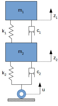
Figure 2: Quarter car suspension
(Source: Litman, 2017, p.221)
The equation of the quarter car suspension is given as:
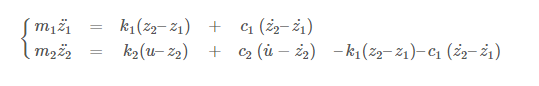
Where m1 represents the mass of the vehicle and m2 is the mass of the suspension along with the wheel . K1 and K2 represent the spring constant of the suspension system and that of the wheel and tire.
Control system of the model
The control system mechanism that is used for controlling the speed of the vehicle is the PID controller. Different implementations are done to control the speed and the steering of the autonomous vehicle. The rear wheel of the bus consists of several gears that are arranged to increase the speed and transmit the power from the vehicle’s rear wheel. A DC motor is present that rotates in the clockwise direction so that the autonomous vehicle can move forward. An Arduino is present which implements the fuzzy logic used to control the mechanism of the vehicle.
ABS Performance
This part of the report explains the application and the performance analysis of the anti braking system of the Hybrid autonomous vehicle. Through the help of Pulse width modulation of the complete process of the anti-lock braking system is initiated. The anti-lock braking system for this vehicle would be determined to form the output value of the torque. The output of the torque for this vehicle would be determined to form the scope that has been connected by the researcher in MATLAB. The barking control system comprises two different braking torques that are applied to the complete system. The anti-lock braking system is considered a conventional method for the sliding controller. This sliding mode controller is completely based on the target slip ratio to the increasing or the decreasing factor of the electric motor that runs on the principle of the Fuzzy logic controller. The braking torques are changed on the abscess of slip ratio to maintain the stability of the vehicle. Therefore through the help of the below-written equation, the torque is monitored or maintained to provide a stable barking system.
Through the help of the above-written equation this may considered as the Th, b, Tmm is considered as the Braking torque and the Tr is considered as the torque that has been involved with the driver.
Brake performance
This part of the report highlights the concept of braking performance of the Autonomous vehicle. The higher positive rate of braking performance leads to higher stability of the vehicle. Autonomous vehicles comprise a salient feature to save fuels through the help of regenerative braking. The high rate of saving fuel leads the vehicle with higher efficiency and also provides higher longevity to the autonomous vehicle.
Discussion and evaluation of the results
This part of the report sheds light on the results that have been extracted from MATLAB. Through the help of MATLAB Simulink, the different parameters of speed control have been determined by the researcher. The complete design of the Hybrid autonomous car comprises several subsystems that have been added by the researcher through the help of Matlab Simulink Library. As commented by Millard-Ball, 2019, p.143, the researcher has executed the process of speed control through the help of MATLAB codes. The researcher has also depicted the complete model of the car and the connected sub-system connected to the integrated circuit. Through the help of MATLAB, the researcher has designed the complete circuit of the Autonomous car.
The developed model of the car comprises vital elements that would help to look at the results of simulation in such a way that would directly help to control the speed of the car. The change in speed has been determined from the different graphs that have been added by the researcher. The different graph has been extracted by the researcher through the help of MATLAB software and the graph has been drawn against the certain parameters such as Velocity, Speed, Time and Current (Kuutti, et al., 2019, p.112). Through the help of simulation in codes, the simulation process would be initiated among the sub-system that has been integrated with the complete circuit. The electrical sub-system comprises the different types of converters that would help deliver the power required to the car smoothly. The electrical sub-system of the car model requires the dc to dc converter, ac to dc motor, and the ac to dc generator. This autonomous developed car model comprises a vital gear mechanism that helps the car to proceed smoothly over the path. The most vital element of the developed Autonomous vehicle is the engine of the vehicle.
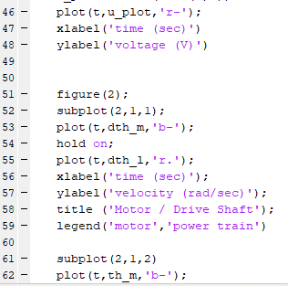
Figure 3: Depicts the MATLAB CODES for speed control
(Source: Self-created)
This above-mentioned figure represents the codes that have been executed by the researcher to represent the change in position, change in speed, and change in speed concerning time. Through the help of these executed codes, the researcher has denoted the parameters that have been placed on the x-axis and the other parameters that have been placed on Y-axis.
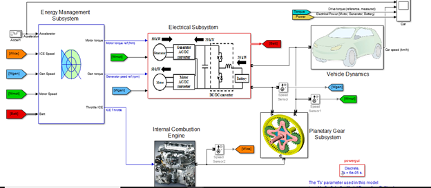
Figure 4: Depicts the complete model of the Car
(Source: Self-created)
The above-represented figure depicts the circuit design and the integration of all components that have been developed by the researcher through the help of MATLAB software. The researcher has added the Energy management system block to regulate the speed of the generator and the motor that has been connected to the bus model. The energy management block comprises significant features to control the speed of the vehicle as per the requirement. Depending upon the speed of the car the Engine of the vehicle works efficiently as a result of proper energy management (Lv et al., 2019, p.112). The researcher has added a gear mechanism to describe the functionality of the gear in such an autonomous vehicle. The researcher has also added one number of scope to determine the Torque and the Power consumed by the vehicle. The scope has been connected to determine the power and the torque at different intervals of time.
Through the help of certain graphs that the researcher has extracted from the MATLAB software reflects the change of position of the vehicle and also reflects the change of velocity concerning time. The time has been measured in seconds in every case of the above-represented concerning above-represented concerning with
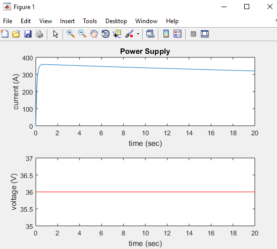
Figure 5: Voltage and Current Graph
(Source: Self-created)
This above-represented figure depicts the Voltage and the Current graph that has been extracted by the researcher through the help of MATLAB codes. Through the help of this above figure the researcher depicts the change of current to the time and the change of voltage to the time. The values of the current and the voltage would be changed with the help of MATLAB codes.
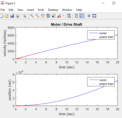
Figure 6: Change of Velocity and Position of the Motor shaft and Time
(Source: Self-created)
The above-represented figure depicts the change in velocity of the car and the change in position of the car concerning time has been represented by the researcher. This change in velocity and the position of the motor shaft of the vehicle has been represented by the researcher.
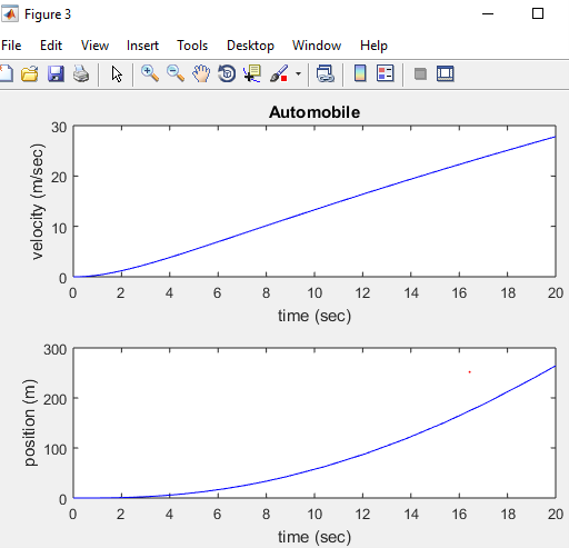
Figure 7: Change of Velocity and Position of the Vehicle and Time
(Source: Self-created)
Through the help of the above placed graphical figure the researcher depicts the change of position of the vehicle concerning time and the change of velocity concerning time. Through the help of MATLAB codes and MATLAB simulation. The researcher has represented the change of speed and velocity of the vehicle. The different graph has been extracted by the researcher through the help of MATLAB software and the graph has been drawn against the certain parameters such as Velocity, Speed, Time and Current
Conclusion and Recommendation
It gets to learn from this report about the vehicles and the system of the vehicles. It can learn from these projects about vehicle technology and the degree of hybridization. The degree of hybridization is used by using the formula Degree of hybridization = power of the motor / power of the motor + power of the engine * 100. In this degree of hybridization, there are 4 types of hybrid, micro-hybrid, mild hybrid, full hybrid, and plug-in hybrid. The macro hybrid saves the power up to 5 to 10%, the mild hybrid saves the power around 20 to 30% and the full hybrid saves the power up to 30 to 50%. The hybrid powertrain has developed; as it gets developed it helps to distinguish the physical deviation between the gallons of diesel and the modern GDI of the engine. An emission control system that works to release the noxious gases which are not needed in the car with the help of ICE. ICE stands for Internal Combustion Engine. At the time of changing the chemical energy to mechanical energy at that time the power gets auto transmitted. Moreover when its energy gets to change and for changing, the vehicle processes to move from one place to another. MATLAB software is used for completing this report. The ABS model is used in this report for modeling the car. ABS model is also known as the system of anti-lock braking. This project also gives the idea about the PID which helps to control the speed of the vehicle.