


Abstract
Control systems for fuel cells need to control the rate of the electrochemical reactions to optimum levels for optimum electrical current supply. In this paper, Proton Exchange Membrane Fuel Cells are studied and its control system designed. A feed-forward controller is used to control the level of hydrogen ions in the cell, while a feedback controller is used to control the other nonlinear systems that influence the electrical current production. The systems controlled by the feedback control are the temperature subsystem, reactants subsystem, the waste product subsystem, and the humidification system. Effective control of the subsystems enables the PEMFC gain more utility in industrial applications. The control system design is done in MATLAB and the impact of varying the controller gains used to assess the impact on the system. The aim is to gain effective control of the fuel cells through simulation.
CHAPTER 1: INTRODUCTION
1.1. Project Definition:
Modern world day-by-day is becoming more concerned towards consumption of natural resources due to the continuous depletion in the level of natural resources. The burning of fossil fuels results in the emission of greenhouse gases such as CO2 which in turn affect the thickness of ozone layer in the atmosphere. Depletion in the ozone layer is majorly responsible for worldwide climatic changes more commonly known as global warming. Due to this in last few decades, numerous researchers are going on across the world to derive cleaner and safer sources of energy for the future world. Fuel cells are considered to be one of the safest energy sources at present (Pukrushpan, 2003). For reducing dependency on fossil fuels one of the widely acknowledged emerging fuel cell technologies is the Polymer Electrolyte Membrane (PEM) fuel cell. Now for achieving optimal performance from the fuel cells, it is required to precisely control the oxygen ratio in the fuel cell stacks. This not only prevents starvation of fuel cells from oxygen but also provides improved control. Several types of research have presented different control methodologies and control systems for fuel cell system control over the years (Carlos, 2009). This project is intended to carry out a review of the different fuel cell control techniques and propose and implement a feed-forward and feedback controller based fuel cell system.
1.2. Problem Statement:
The development of the fuel cell is one of the most important electricity production strategies for the future since it will provide a stable energy source even for automobiles. It does not need recharging, hence it will not leave the users stranded in case they are not close to an electrical power supply. The components of the system only need hydrogen and air, hydrogen can be stored in a hydrogen tank while the air (oxygen) is derived from the atmosphere. In the fuel cell, there needs to be a right mix of the inputs and the right temperature for the electrolyte to produce an optimum power supply (Yin and Chang, 2011). It is the role of the designers to determine the optimum operating conditions for optimum power supply while ensuring the durability of the system.
Providing optimum conditions involves feeding the system with the right quantity of hydrogen gas, which means the flow rate of the hydrogen gas into the cell has to be determined. Similarly, the right quantities of oxygen have to be introduced into the fuel cell at the correct mass flow rates. If there is a lean mixture of the hydrogen and oxygen, the system will be starved and will underproduce the electricity. If the system is fed with too much of the inputs, there will be a wastage, the excess inputs will also hinder effective electrolysis. A rich mixture of the hydrogen-air combination in the electrolyte at the anode and cathode side is needed (Reddy et al., 2010).
In the fuel cell there needs to be an optimum temperature at which the electrolyte operates, hence the hydrogen is oxidized to a proton while the oxygen is reduced to and oxygen ion. At the right temperature too, the heat loss or heat gain from the system will not cause a disturbance in the current production. Apart from the mass flow rates of the inputs and the thermal conditions in the cell, there is a need for a control of the chemical reactions. The Red-Ox reductions may at times produce too much hydrogen ions in the cell leading to an unstable current supply in the electrolyte. The major role of the subsystems is to ensure the chemical reactions are consistently stable so that hydrogen ion production is within the optimum limits (Hwang, Wang and Kuo, 2012). Finally, the other subsystem is the waste product subsystem that drains the water out of the fuel cell. If this subsystem is not well modelled, the water will accumulate in the fuel cell and prevent the optimum operating conditions. It will hinder the optimum thermal conditions and the inflow of the reactants to the system.
The integration of all these systems enables the realisation of the desired operating conditions. The design in this paper will focus on how to come up with the best control system for the operation.
1.3. Problem Solution:
The control system of the fuel cell will be modelled from the first principles to come up with the desired controllers. As stated in the problem, a control system for the inputs to regulate their mass flow rate, a control of the thermal conditions in the cell, a control of the electrolysis where hydrogen is oxidised and the oxygen is reduced and the control of the by-product of the reaction process (Franklin, Powell and Emami-Naeini, 2002).
The modelling involves coming up with differential equations that characterise the operation parameters, these differential equations are then simplified to Laplace transforms that will help come up with the transfer functions of the control systems. All these systems will be integrated into one control system and modelled in MATLAB & SIMULINK. Design of the control system in MATLAB helps come up with an efficient system of interconnecting the different control subsystems to ensure the response output of the system is within the desired control operations (Singh and Agnihotri, 2001). The disturbances in the system will be reduced to ensure the error from the output is reduced to zero when compared with the input signal.
In the control design, a closed loop control system is used rather than the open loop system. The closed system employs the feed-forward and feedback control system is used to regulate the operating conditions in the fuel cell. The feed-forward control is specifically used to regulate the concentration of hydrogen ions in the cell while the feedback system is used to gauge the performance of the other subsystems to ensure its efficient operation. The feed-forward controller will use the proportional-only control since it is assumed to be a linear system that monitors the level of hydrogen ions in the fuel cell. The feedback control system is meant to be a higher order system since it is meant to control a variety of aspects in the fuel cell. Higher order systems are non-linear and present high instability in the system, these will be controlled by the PID controller (Ulsoy, Peng and Çakmakci, 2012). In the simulation process, the gain of the PID controllers will be iterated to find the optimum transient response and achieve the best control.
It is the intention of the control system design process to come up with a system that is unmanned, only the current production levels are to be set and the system adjusts itself to match the power requirement characteristics. The automated control systems will ensure that it is easier to run devices operating on fuel cells without a power surge or short-circuiting that damages the electrical and electronic devices. This will, therefore, match the efficiency of operation reducing the maintenance costs and the green-energy requirements for durable and long-term applications.
1.4. Importance of the Project:
Optimal control of fuel cell system improves its performance in terms of power density, durability and operational as well as maintenance cost. Several researchers have proposed different fuel cell control strategies. In order to select the optimal control strategy, it is required to carry out analysis of the proposed control strategies (Youngseung et al, 2015). This project will investigate different fuel cell control strategies and analyse applicability, advantages and shortcoming of each of the strategies. Finally through simulation one of the most suitable strategies will be evaluated and analysed. As a whole, this project report will act as a guide for the selection of control strategies for a fuel cell system.
Fuel cells are used for producing electrical energy along with chemically released heat energy and water. On the anode side of the fuel cell, hydrogen is consumed whereas the cathode side of the fuel cell consumes oxygen. In the fuel cells, reactants come in and products of reaction go out keeping the electrolyte within the cell (Nehrir et al, 2009). The major difference of fuel cell from batteries comes from the fact that fuel cell does not require to be recharged. Operation of the fuel cell is also more efficient and quieter. The fuel cells are a perfect source of green energy. The electrical power from the systems has zero emissions.
The PEMFC specifically has very little noise in its operation while the heat produced is very little. This makes it more usable in the domestic environments due to its safe operating levels (Ragb et al, 2012). When compared to solar panels and wind turbines, the fuel cells occupy less space. To produce the same power output, the solar panels will occupy more area per watt-hour while the wind turbine will require more space for ease of rotation of its blades, the wind turbine noise levels are sometimes irritating too. Due to its small size, they can easily be moved from a location to another for convenience its application in remote areas not accessed by the national grid. Fuel cells are superior to batteries because they do not need recharging and provide power for longer periods. For the fuel cells, power is produced as long as there is fuel (compressed hydrogen), meaning it will produce power for longer sustained periods.
1.5. Aim & Objectives:
The aim of this project is to promote the efficiency of fuel cell system and save fuel
Following are the project objectives:
- Modelling the fuel cell system with MATLAB simulation:
Based on literature findings a simplified PEM fuel cell system with critical components needs to be modelled using MATLAB/ Simulink software
- Designing feed-forward controller:
Mathematical formulation of a feed-forward controller for the designed fuel cell system needs to be carried out. This formulation needs to be implemented in MATLAB/ Simulink.
- Designing feedback controller:
Mathematical formulation of a feedback controller for the designed fuel cell system needs to be carried out. This formulation needs to be implemented in MATLAB/ Simulink.
- Evaluation of the designed control system performance with MATLAB simulation:
Simulation of the fuel cell model along with feed-forward and feedback controller needs to be carried out for validating whether the performance of the fuel cell system has improved through controllers or not.
- Writing a formal report and preparing for Viva + presentation:
A final report detailing all the findings of the project will be prepared in specific University approved format.
1.6. The Scope of work:
The work involves the study of the operation principles of the fuel cell to determine the how best the control system can be designed for efficient operation. The operation of other fuel cells will be studied to derive a perfect control system for the Polymer Electrolyte Membrane cells. The control system is modelled by the differential equations that describe the interconnection of the different parameters for optimum operation. The ideal system is modelled in MATLAB & SIMULINK programming. Finally, a recommendation is given for the future control systems for the operation of the fuel PEM cells. Other considerations and assumptions will also be highlighted.
CHAPTER 2: RESEARCH
2.1. Fuel Cell – An Alternative Green Energy Source:
There is rapid decrement of fossil fuels globally in spite of the new discoveries of major fossil fuel reserves. The demand for energy is increasing so rapidly that in very near future fossil fuel alone will not be able to maintain demand-supply chain of energy. Thereby world’s energy security is under threat. Apart from that several other global concerns about the environment such as unexpected climatic changes, global warming and acid rain are promoted by the burning of fossil fuels. Due to this in last few decades, there have been huge investments on the researchers for finding out sustainable, renewable and alternative sources of energy both by the government and privately funded institutes, companies and research centres (Carnevalia et al, 2017). The aim of these alternative energy sources is to bridge the gap in demand-supply not only at present but also in future. There are several different alternatives and renewable energy sources explored by scientists such as wind energy, biomass energy, hydro-electrical power, solar energy, nuclear energy, geothermal energy etc. One other critical and potential alternative energy source identified is hydrogen energy. Fuel cell technology falls under this particular category of alternative energy source (Nehrir et al, 2009). Fuel cell technology is considered to be one of the most prospective clean and green energy sources because of it is zero or minimal pollutant emission based on whether produced hydrogen is from renewable or non-renewable sources. Energy efficiency of the fuel cell is also much higher compared to the other alternative sources of energy discussed earlier (Gou et al, 2017).
2.2. What are Fuel Cells?
This is a type of an electrochemical cell that converts the chemical energy to electrical energy by the reaction of hydrogen and oxygen. The difference between the fuel cell and batteries is that fuel cells need a constant supply of the fuel and oxygen into the system while batteries have their in-built reactants. The fuel cell systems are designed to provide electrical energy as long as the fuel (hydrogen gas) and air (oxygen) are allowed into the system. The type of fuel cell will depend on the type of electrolyte used in the system, and this will also determine the efficiency of the fuel cell in electrical energy production (Myers, 2001).
Fuel cells generally have higher efficiency and provide clean energy for use in the different applications. This is because the ideal by-product of the system is water. The concept of fuel cells began when there was a need for the invention of an efficient source of electrical power that does not pollute the environment. The cell is not like electric devices that require constant access to electrical power to charge the batteries, rather the system needs constant hydrogen sources, atmospheric air can be used to provide the oxygen.
The use of fuel cells is currently limited because the initial cost of manufacture is high, making the costs to acquire it rather high too. Even though the initial investment is high, the long-term savings and benefits far outweigh the initial costs. They do not only serve as backup sources of electrical power but can be relied on as sustainable electrical power sources.
2.3. Different Types of Fuel Cells:
In general the fuel cell technology can be broadly categorized into six classes based on their working principle and applications: proton exchange membrane fuel cell (PEMFC), molten carbonate fuel cell (MCFC), direct methanol fuel cell (DMFC), alkaline fuel cell (AFC), phosphoric acid fuel cell (PAFC) and solid oxide fuel cell (SOFC). One other promising technology in fuel cell emerged in recent years is microbial fuel cell (MFC). These different classes of fuel cells differ majorly with respect to the fuel and electrolyte (Daud et al, 2017).
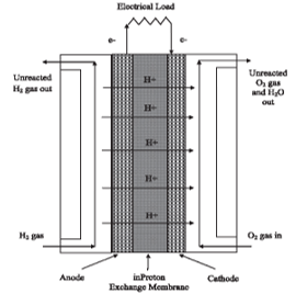
Figure 1. Structural schematic of a PEM Fuel Cell (Daud et al, 2017)
The most common and most promising variety of fuel cells widely acknowledged across the world is a proton exchange membrane fuel cell (PEMFC). This is because of its zero to minimal pollutant emission making it one of the cleanest energy source and its ease of commercialization on a large scale. PEMFC offers lots of advantages such as higher power density, lower operating temperature, lighter weight, the capability of quick startup and lowers noise. These fuel cells have found applications in office buildings, hotels and hospitals as small-distributed power generators. The power rating can vary from 1 kW to 5 MW. In portable electronic devices such as mobiles and laptops 20 – 100 mW PEMFCs are used in place of batteries. This is mainly because of their compact and smaller size, lighter weight, no requirement of grid charging and faster response time (Kirubakaran et al, 2009).
In last few years with respect to usage in mobile phones DMFCs have mostly captured the places for PEMFCs. This is because of the ease of carrying liquid fuel methanol in small quantity in DMFCs in comparison to carrying hydrogen in PEMFCs.
Due to the scarcity of fossil fuel and thereby continuously increasing fossil fuel price PEMFCs can be used as a potential energy source in transportation sectors. These can replace the conventional internal combustion engines used in cars, buses and two-wheelers. This will in turn reduce the pollutant emissions from the vehicle, which is also a major concern for researchers, scientists and government regulators across the world (Torres et al, 2017).
2.4. Components of the PEM Fuel Cells and how they work.
The components and the working of a proton exchange membrane fuel cell are demonstrated in the figure below:
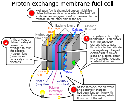
Figure 2: The PEMFC
The components are as shown in the schematic in figure 1 and in figure 2. They mainly consist inlets which are the injection tubes for the reactants. On injection tube is for the fuel (hydrogen gas), the other injection tube is for the air. The next component is the casing that houses all the components of the fuel cell. It also has an outlet tube for draining away the wastewater from the electricity production process. The system also has a tube to pass the unused gas that is recycled back to the system.
The major functional components are the anode and cathode, and the electrolyte. The electrolyte, in this case, is the proton exchange membrane. Hydrogen is oxidized at the anode side to a proton, it travels to the cathode side where it combines with the oxygen ion to form water (Kiatkittikul, Nohira and Hagiwara, 2015). Oxygen, on the other hand, is reduced at the cathode side to form an oxygen ion, this combines with the hydrogen ion to form water. The electrons lost at the anode side travel through the conductor to form a current.
The system works by pumping the fuel into the cell via the inlet ducts. Both the anode sides and cathode sides have a platinum catalyst that converts the molecules of the reactants to ions. After the platinum catalysis is the proton exchange membrane. This membrane allows only the protons (hydrogen ions) to pass through it since they are positively charged. The electrons cannot cross the membrane, rather they travel along the conductor to the cathode side to create a current. At the cathode end, the hydrogen ions then combine with the oxygen ions to form water (Subhasree and Kotteswaran, 2016).
The oxidation-reduction process in the fuel cell is less noisy and produces less thermal energy. They can be applied to domestic use and other electrical appliances that will not require shielding from the high heat. As mentioned earlier, if high current productions are needed, the cells are stacked parallel and if high voltage production is needed the cells are stacked in series.
2.1. Applications of the Fuel Cell:
Fuel cells have wide domestic and commercial applications. They are light in weight, portable and long-lasting. This makes them superior to the use of rechargeable batteries. All that is needed is the constant supply of the fuel, which can be compressed liquid hydrogen that is allowed into the fuel cell at the desired rates. A single cell cannot produce much power to suit high performance requirements, in most cases, the cells are stacked and connected depending on its final use. For a high current application, the cells are stacked in parallel to each other while for high voltage applications the cells are stacked in series. Some of the common applications of fuel cells are stand-alone power provision in commercial buildings and domestic applications, used in automobiles either in hybrid systems or stand-alone systems. The fuel cells for stand-alone power provisions for commercial applications are larger to produce more power to meet the high demand for such systems (Ulsoy, Peng and Çakmakci, 2012). Fuel cells can also be used in hybrid systems where the can be backup power for the micro-grids or power from the national grid. When used in such systems, the fuel cells have to be connected to supercapacitors, batteries or other storage systems together with effective control systems to draw the required power when needed. Some of the applications of fuel cells are highlighted below:
- As a portable power source:
Since the Fuel Cells are light in weight, portable and long-lasting, they are efficient power sources in areas where there is no access to a grid supply. It makes it convenient to provide power to mobile devices or equipment without increasing the payload to extreme levels. When compared with the fuel cells, the rechargeable batteries are heavy and not flexible to produce the optimum power supply for niche requirements (Esposito and Conti, 2009). To produce the same power with the fuel cells, larger and heavier rechargeable batteries are needed which may not be economically viable in most circumstances.
- Efficient source of backup power:
Power for backup is used when the main electrical power source fails. This application is mainly in the industries where backup power is needed when the conventional sources fail. For heavy applications, higher power fuel cells are used while for domestic or small-scale applications, smaller sized cells are used. The PEM fuel cell with compressed hydrogen is specifically suitable to provide backup power in case the common sources of power fail.
- Transport applications:
The use of fuel cells in the transport industry is viable. The cells can power buses, cars, scooters and other automobiles. The size and properties of the fuel cell will thus depend on the power requirements of the system. For instance, small size fuel cells may be used for the start-up of the main engines, while large fuel cells giving high power are used for propulsion of the vehicle. The fuel cells can be used also in cranes, forklifts boats, wheelchairs and airport movers among others for stable power supply in operation (Kiatkittikul, Nohira and Hagiwara, 2015).
- Stationary power applications:
When the fuel cell is to be used as the main power supply system for a given location, the choice is dependent on the type of fuel cell and the cooling system of the stacks. The fuel cells are perfect for micro-grids or providing supplementary power to micro-grids (Myers, 2001). Sometimes hybrid systems that combine fuel cells, solar power and wind power are efficient in being used to provide electrical power to the areas that are not connected to the national grids. The micro-grid power requirements will, therefore, determine the operational characteristics of the fuel cell required.
2.2. Control of PEM fuel cell system:
Majority of the potential applications of PEMFC require much higher current and voltage, which are not possible to generate through a single fuel cell. So it is a common practice to use stacked PEMFCs in which number of PEMFCs are stacked in series to generate higher voltage and number of PEMFCs are stacked in parallel to generate higher current. Therefore rather than controlling a single fuel cell control strategies of a PEMFC is concerned with controlling the entire stack of the fuel cell in order to achieve maximum electrical power (Carlos, 2009).
The basic working principle of the fuel cell is presented by William Grove in 1839. There are several different fuel cell technologies and configurations used nowadays. Among this, one of the most developed fuel cell technology is the polymer electrolyte membrane (PEM) fuel cell (Gou et al, 2017). These fuel cells depict improved power density, low-temperature operation, reduced corrosion and longer stack and cell lives. This project work will focus on controlling hydrogen-oxygen ratio in the PEM fuel cell stacks (Pukrushpan et al, 2002).
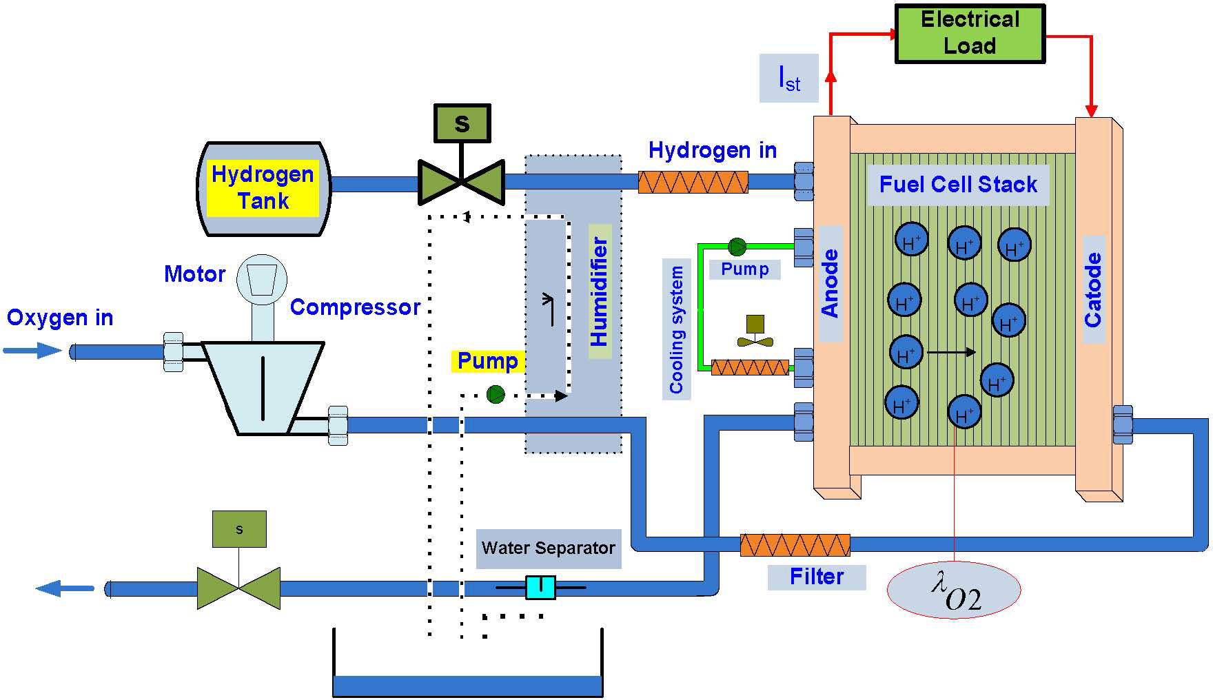
Figure 3. The typical working layout of a PEM fuel cell stack (Ragb et al, 2012)
In case the load draws more current from the fuel cell voltage developed by the stack is reduced due to the phenomena are known as the polarization of PEMFC, this can significantly affect the performance. Therefore controllers need to be implemented in such a way that it can control the air and hydrogen flow rate so as to control the output voltage. Apart from that controllers can also boost the output voltage through the use of external means such as super capacitor or battery (Gabin et al, 2010).
There is another performance related issue encountered in PEMFC stacks known as a slow cold start. At a lower temperature, it becomes difficult for starting the PEMFC stack quickly due to the slowed down fuel cell dynamics because of stacking. Apart from that stacking of a number of fuel cells also significantly increases the temperature. Uncontrolled higher temperature can ultimately result in softening and even destroying the membrane. In single PEMFC natural convection is enough to diffuse the heat generated due to chemical reaction. There is also a requirement of uniform distribution of air and hydrogen gas at the cathodes and anodes of each fuel cell for obtaining uniformity in generated voltage and current from each cell. This requirement also cannot be met without using suitable controllers (Strahl et al, 2017).
Besides this, in order to start a PEMFC stack after a long time, it is required to carry out purging of stored oxygen which is seeped into the anode from ambient. It is also required to mix leftover hydrogen gas from last operating cycle. If this is left uncontrolled, it can result in the very high voltage at the start-up of the stack and can ultimately result in quick degradation of anodes.
To generate higher current and power from the PEMFC stack it is required to keep the membrane sufficiently wet during the operating cycles. Fuel cells also generate water at the cathodes due to electrochemical reactions. Therefore it is required to precisely control the water flow to and from the PEMFC stack to avoid flooding of electrodes and scarcity of water in cells (Nehrir et al, 2009). The design of control systems for the PEM fuel cells is meant to achieve control of the four major subsystems. These are the thermal subsystem, the reactants subsystem, the water management subsystem, the power conditioning subsystem and the power management subsystem. All these subsystems ought to be perfectly coordinated for optimal efficiency and operation.
The reactants flow subsystem is used in regulating the air and hydrogen supply to the fuel cell. This ensures that the adequate reactant is supplied for fast transient response and less auxiliary power consumption. The oxygen supply system is composed of an air compressor that supplies compressed air from the atmosphere, the hydrogen supply system is composed of a pressurised tank and a control valve that releases the hydrogen gas at the required rate.
The thermal subsystem is meant to ensure that there are optimum temperature levels for the reactants to produce optimum power levels. It includes the fuel stack cooling system and the reactant heating system. Cooling the stack is done by a fan or a water refrigeration system, efficient temperature control helps achieve the desired power output levels. The water management subsystem is meant to ensure there is an efficient water supply or removal after its formation. As much as water is a waste product of the system, the performance of the polymer membrane is dependent on a level of hydration. Achieving an adequate water balance will ensure that the system operates at the desired output levels (Esposito and Conti, 2009). To achieve the preliminary control, both air and hydrogen are humidified before entering the fuel cell, the by-product water from the reactants is also collected by a water separator and pumped back to the humidifier for recycling.
The power conditioning system is meant to regulate the DC voltage drawn from the system. In the operation of the fuel cell, there is bound to be an unstable supply of the DC, voltage. There is need to use voltage regulators to stabilise the voltage and current in the system. Sometimes the system may be connected to other power sources like batteries. In this case, a power management subsystem is needed to control the power of these sources since they are often used to charge the super-capacitors or batteries. The power management system is meant to ensure there is the optimum and efficient power supply to the batteries (Reddy et al., 2010). In case full load power is to be supplied, the power management subsystem is not necessary. The aim to be achieved is coming up with a control system that integrates all these subsystems.
The major disturbance identified is the unstable concentration of hydrogen ions in the stacks/ electrolyte. This produces the unstable current supply to the load. To control the system, feedback control systems have been actively used. The use of the feedback mechanism controls the temperatures, reactant supply, and the water subsystem but it does not effectively control the reactant subsystem, more specifically the hydrogen inlet into the fuel cell. Even though, previous papers endeavoured to come up with efficient control of the power supply, modelling the system was often elusive because the subsystems operate at different optimum levels. And individual approach to each of the systems is meant to ensure the correct modelling achieves the desired output levels.
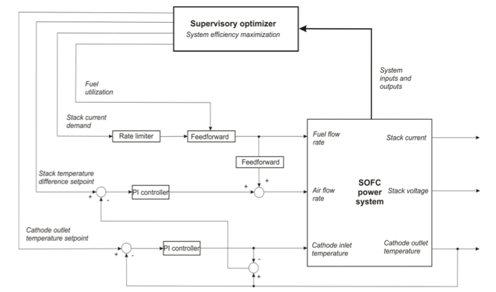
Figure 4. Sample layout of feed-forward and feedback control of a fuel cell system (SOFC, 2014)
The above figure represents a sample layout of feed-forward and feedback control of a fuel cell system. In this figure, there are two feed-forward controllers and to PI controllers. Each PI controller acts as a feedback controller. A similar layout of the controlled PEMFC stack system will be designed first. In that layout, all the required inputs and outputs will be finalized in this phase of the project.
The approach taken by the paper is to design a feed-forward control to regulate the level of hydrogen in the fuel cell, while the feedback systems to integrate all the other subsystems to achieve the desired parameter optimisation. The P-only feed-forward control is used to regulate the level of hydrogen in the fuel cell while the PID feedback control is meant to achieve the desired levels of the other systems. P-only control is used to control linear systems that are proportional whose disturbance is proportional to the levels of input. The PID control is used for higher-order systems whose disturbance is non-linear and unstable (Wang, 2008). The modelling of the other subsystems are nonlinear and will need a PID system to increase the response time and its stability. An iteration of the control mechanism is made for simulation purpose. The output reliability is simulated in MATLAB and Simulink. This ensures comparison between the subsystem and the output of previous research.
2.7. The Theory of Control:
Modelling control systems in engineering need a background understanding of the control theory. The basic functions that define the response of systems to forces or energy are first developed from first principles through dimensional analysis. For control engineering purposes, the parameters that define the systems operating points are modelled in differential equations that transformed to Laplace functions. The Laplace functions are best suited to be modelled as transfer functions for control system modelling. The signal response of the systems to control can then be monitored as the designer works to achieve stability or instability as required. Stable systems are needed for commercial applications where the users are the general public who need systems that work with excellent damping (Ulsoy, Peng and Çakmakci, 2012). Unstable systems are majorly used in military applications for ease of manoeuvring obstacles and enemy missiles in the battlefield. For example, the jet fighter aircraft are manufactured with high instability so that they easily perform the yaw pitch and rolls to evade the enemy attacks at a very fast speed.
Electrical systems are modelled through the Kirchhoff’s current and voltage laws, mechanical systems are modelled depending on the mass balance, the material constants and other mechanical properties of the systems depending on the forces the material has been subjected to. Thermal systems are modelled through the laws of conservation of mass and heat transfer thermodynamics (Ellis, 2004). For systems that combine thermodynamics, electrical and mechanical systems, modelling will integrate all the applicable laws to come up with a system that defines the operating points. In this task, the operation of the system is dependent on thermodynamics, chemical reactions and electrical systems. The integration of all these systems produces an electrical current in the conductor. Therefore, the design of the control system will consider the different parameters of operation.
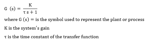
The system developed is a second-order system, therefore a second-order transfer function is used to come up with the MATLAB & SIMULINK model. The PID feedback controller together with a P-only feed-forward controller is used in achieving the effective control mechanism. P-only control is used in first order system where the disturbance is linear. The gain selected will depend on the output to be achieved by the control system. If the amplitude of the output is to be reduced, a gain of lower than 1 will be selected, and if the amplitude of the system is to increase, a gain of higher than 1 will be selected. The transfer function for first-order linear systems is represented below:
Higher order transfer functions are always non-linear and cannot be effectively controlled by P-only control. This is because the disturbance in the system is not proportional to the input. To come up with models for such systems, a PI control is used. This controller achieves higher accuracy since the inclusion of the integral controller increases precision (Wang, 2008). The use of this two controller sometimes lowers the stability of the system. The derivative term is introduced if higher stability and the higher response speed are needed. Therefore, control of higher order transfer functions is achieved by the use of the PID controllers. An example of a higher-order complex transfer function is shown below:
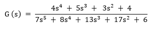
The equation above is a 5th order transfer function because the highest power in the denominator has a power of 5. The output of such a system will be nonlinear due to the interaction of the values in the numerator and denominator. Controlling such a system will depend on the tuning of the controllers to achieve the desired output. The simulation of the ideal control system is performed in MATLAB and SIMULINK or other design software that best achieves the control mechanism.
2.7.1. The PID controllers
They are also referred to as the three-term control. This combine gains from three controllers; the Kp, Ki and Kd. When they are fully combined in one system, they achieve the best control. The combination of the three-term control mechanism is achieved by the mathematical equation below:
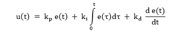
Where u(t) is the corrected signal, 


The block diagram of PID control is shown in the diagram below:
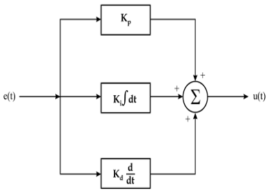
Figure 5: The PID control block diagram demonstration
Feedback control uses the PID to achieve the desired effect. The diagram below shows how a feedback PID control is used together with the feed-forward control to control a system.
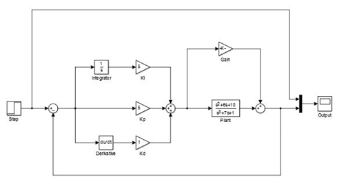
Figure 6: A control system with PID feedback and P-only feed-forward control
In the diagram, the step gives the input signal that goes through the controllers before it gets to the plant. From the plant, the output signal goes to the output display. The role of the multiplexer between the plant and the output is to multiplex the output and the input signal so that it can be compared. In the block diagram above (figure 6), the output signal is fed back to the system. The error signal (the difference between the input and the output signal) is fed to the PID controllers to correct the signal. The corrected signal is fed to the plant. However, there is a feed-forward signal that corrects a certain parameter in the plant. All these controllers are meant to achieve effective stabilisation of the output in the system. They improve the accuracy and stability of high response speeds. The control systems tune them to suit the application.
CHAPTER 3: PROJECT PLAN
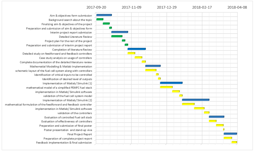
3.1. Detailed Project Plan:
22nd September – 13th October 2017:
- Carrying out background search about the topic. This involves a background study on fuel cells, their applications, the benefits, the disadvantages and the problem that ought to be solved by the system designed.
- Finalizing aim & objectives of the project: this states the objective of working on the project and effective means of achieving the solutions.
- Preparation and submission of aim & objectives form
14th October – 5th November 2017:
- For developing understanding of the working principle of fuel cells, controllers controlled fuel cell operations relevant literature in the form of journal publications, online articles, books and conference proceedings are referred
- Project plan for the rest of the project is formulated
- Findings of the literature review carried out so far have been documented
- Preparation and submission of interim project report
6th November – 30th November:
- A detailed study on feed-forward and feedback controllers with respect to a mathematical formulation, physical interpretation, advantages and limitations
- Case study analysis on usage of feed-forward and feedback controllers in fuel cells
- Complete documentation of the detailed literature review
1st December – 21st December:
- Preparation of the schematic layout of the fuel cell system along with controllers based on theoretical findings
- Identification of critical inputs to be controlled using feed-forward and feedback controllers
- Identification of the desired level of outputs to be achieved
22nd December 2017 – 21st January 2018:
- Based on the identified inputs and outputs a mathematical model of a simplified PEMFC fuel stack will be designed
- The mathematical formulation will be implemented in MATLAB/ Simulink software
- With known inputs and outputs simulation of the model will be carried out to validate the fuel cell system model
22nd January – 28th February 2018:
- As per design layout, mathematical formulation of the feed-forward and feedback controller will be carried out
- The mathematical formulation will be implemented in MATLAB/ Simulink software along with the fuel cell stack model
- Some test cases will be simulated to check the working of the controllers
1st March – 21st March 2018:
- Based on case study analysis suitable controller validation data will be collected
- With specified inputs, fuel cell stack model will be run with and without controllers
- Results of simulation will be presented in a graphical and tabular form for ease of comparison
- The effectiveness of the controllers will be evaluated through evaluation of performance improvement of the fuel cell stack with same inputs
- Preparation and submission of final poster
- Poster presentation and stand-up viva
22nd March – 8th April 2018:
- Preparation of complete project report in a specified format with all the project findings
- Implementation of feedbacks from the tutor and final report submission
CHAPTER 4: FINDINGS
This section discusses the mathematical models found to suit the system. Through coming with the mathematical model, it will be easier to model the system in MATLAB. The findings, therefore, discuss coming up with the mathematical models that define the operation of the subsystem for modelling.
4.1. Mathematical modelling of the system:
The redox reaction that enables the flow of electrons and generation of current in the conductor is shown below:
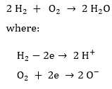
The process gives electrical current and water as the by-product (Timurkutluk and Mat, 2014).
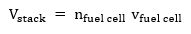
The electrochemical reaction above happens in the fuel cell stacks, at the anode side of the stack, hydrogen is fed while at the cathode side the oxygen is fed. To perfectly model the system, four sections are modelled. These are the membrane hydration model, the cathode mass flow model, the anode mass flow model and the stack voltage model. Through getting the possible voltage levels of the system, it is possible to determine the other operational parameters of the system for modelling. The stack voltage is given by the equation below:


In the equation above 

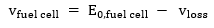
In the Nernst equation, 


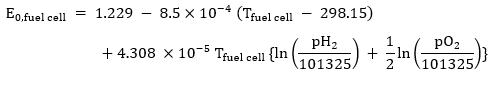
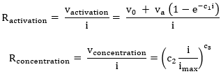
The activation loss is found by 


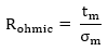
The ohmic losses in the cell are calculated as shown below:
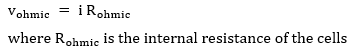
The internal resistance is the quotient of the membrane 

The conductivity of the membrane can be calculated as below.
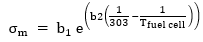
The values for b1 and b2 are membrane conductivity constants, they can be found from the properties of Nafion 117 since it’s the material used in building the stacks of the fuel cell (Esposito and Conti, 2009). Finally, the concentration losses are calculated by:
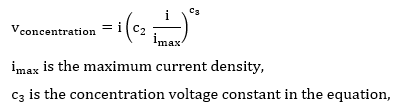
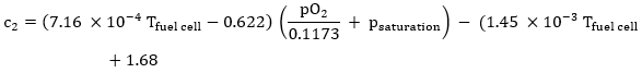
While c2 is dependent on the water saturation pressure, the oxygen partial pressure and temperature as calculated below (Timurkutluk and Mat, 2014):
In case the fuel cell operates at a low pressure, the value can be computed as below:
The calculated voltage voltages of the fuel cell are thus calculated as in the equation below:

The electric model developed was dependent on the parasitic capacitance of the static model. The modelling was implemented by finding the activation resistance and the concentration resistance that led to the respective losses.
The current-voltage relations for the fuel cell can thus be written as:
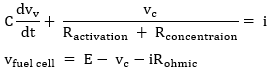
These two equations are used to come up with the transfer functions for modelling the system. They were combined as below, s is the Laplace operator in the equation.

The equation above is a first order transfer function and is effective in achieving the feed-forward control for the hydrogen ions, since it is the quantity of hydrogen ions that determines the voltage and current output in the conductor (Reddy et al., 2010). However, the equation is not sufficient in modelling all the systems of the fuel cell. For instance, the equation does not consider the flow rates of the reactants, the heat transfer of the reactants and the heat transfer in the cell.
According to Subhasree1 and Kotteswaran (2006, p.3), the equation they used to model the PEM cell was a fifth order equation shown below. This equation gave 99.95% fitness to the original data they found in their experimental analysis. It considered all the subsystems and all the constraints in the analytical process. It was found through dimensional analysis of all the constituent parameters. The equation is used to model the control system for the model developed in our case study.

The transfer function above is modelled in MATLAB using a feed-forward control and a feedback control system to ensure a stable electrical supply signal is achieved. For the feed-forward controller, a P-only control is applied since only one linear parameter is controlled, this is the amount of hydrogen ions in the fuel cell. This is achieved by controlling the valve that allows the hydrogen into the fuel cell from the hydrogen compressor. The feedback control system uses the PID control since all the other parameters like thermal subsystems, the reactant subsystem, the humidification of the fuel, air and the cell stacks all are nonlinear higher-order functions.
In the simulation, the gain values for the controller are tested and tuned through an iteration process that helps come up with the correct values. The basic values for the Kp, Ki and Kd are selected from intuition based on the output signal without any controller. For instance, at the first iteration, Kp of 1 is chosen while Kd and Ki are kept at zero, this is done until the signal is stabilised. Then Ki is chosen to reduce the response time and finally Kd chosen so that it will stabilise the system.
CHAPTER 5: DISCUSSION
This section discusses the modelling of the equations of the higher order transfer functions found in the previous section. It models the transfer function of the system without the use of any controller, with the feed-forward control only, then with the feedback control system. It gives a thorough discussion of the output from the simulation. The closed-loop model is used since the PEMFC needs feedback on the operational output rather than having an open loop system. The block diagram of the feedback feed-forward system is shown below:
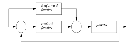
Figure 8: Block diagram of feedback and feed-forward system
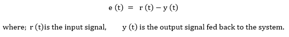
The feed-forward action anticipates the disturbance in the plant (process) and tries to regulate it so that the output can be stable (Singh and Agnihotri, 2001). On the other hand, the feedback control system is used in correcting the error in the output. This signal is feedback to the comparator where the difference between the input signal and the output signal is compared. The error (differences in the two signals) is fed to the PID controller for correction and stabilisation.
In the system modelled, the feed-forward control is to control the disturbance in the cell which is the level of hydrogen ions. Higher concentration of the hydrogen ions leads to unstable current output in the conductor, it may also lead to higher heat production, de-humidification of the fuel-cell stacks and other suboptimal conditions that hinder effective current production (Kiatkittikul, Nohira and Hagiwara, 2015). If the correct level of hydrogen ions is produced at the cathode in the fuel cell, the other subsystems can be effectively optimised to match the level of hydrogen ion production. In summary, the operation of the other subsystems is dependent on the level of hydrogen ions in the cell. From the level of the output voltage, the other systems will be adjusted to match the level of hydrogen ions in the fuel cell.
The sequence in achieving the control are highlighted below:
- Simulation of the system without any control mechanism: the purpose in this section is to assess the response of the system without any control mechanism so that after applying control, it will be easier to compare the controlled output and the uncontrolled output.
- Using the feed-forward controller: the hydrogen ion fluctuation in the fuel cell is one of the anticipated disturbances in the system. The feed-forward control is used to help check the level of hydrogen ions. Trying to achieve the effective Kp value for the feed-forward controller is a preliminary task, the value of Kp is then adjusted later to achieve the best output.
- Introducing the feedback system: the introduction of the feedback system without the feedback controller just eliminates the large error between the input and output and feeds the corrected signal to the plant. No control is effected in this section, but the error between the output and the input is greatly reduced.
- Introducing the PID controller: the PID controller is modelled in steps. The first model is introducing the Kp only control, then the PI control is introduced. Finally, the Kd control is introduced to reduce the increase the response time and to stabilise the signal.
- Adjusting the value of the gain for the feed-forward controller. This section re-adjusts the value of gain for the feed-forward controller to achieve the desired output levels for the entire control system.
- Comparison of the system with the effected feed-forward feedback control and the system without any control mechanism.
Working on these sequentially will bring out the effect of each controller on the output of the system.
5.1. The Simulink Model without any controller:
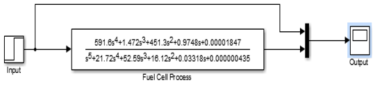
Figure 9: Modelling the system without any controller
In the control system above, the transfer function describes the fuel cell process, the step used in the process is 5V. The input and the output signal are multiplexed and displayed in the output scope display. The output for the system without any controller is shown in the graphical plot below:
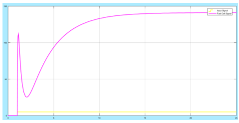
Figure 10: The output of the signal without any feedback or control
In the diagram above, the step input is the 5V, this is the activation voltage. The fuel cell has an output transfer of about 140 volts. The signal is unstable in the first 5 seconds but rises steadily and becomes stable after approximately 15 seconds. This is attributed to the fast increase in the hydrogen ions in the fuel cell after its introduction, but its stabilisation is after all the sub-systems work to achieve the desired optimum. A feed-forward controller is therefore needed to control the level of hydrogen ions in the fuel cell within the required time. A proportional only controller constant used will either increase or decrease the level of hydrogen ions proportionately in the system. Having a value greater than 1 will increase the concentration of hydrogen ions while a value less than 1 will decrease the level of hydrogen ions. The designer will always want higher output voltages from the fuel cell, therefore, a gain of 5 is used for the preliminary analysis. The block diagram and the output is shown in the figure below:
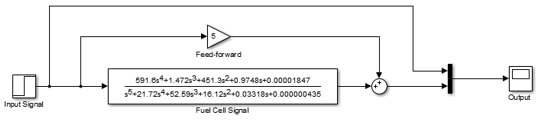
Figure 11: The feed-forward control with a gain of 5
The block diagram above shows the feed forward with a gain of 5. This will increase the level of hydrogen ion concentration in the cell and in turn increase the output voltage levels. The comparison between the output and input signal is shown in the figure below:
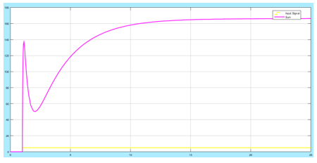
Figure 12: the input and output response of the system
In the plot, a gain of 5 increases the output signal voltage to greater than 150 as compared to the signal without any gain (about 140V). The gain of the feed-forward increases the concentration of the hydrogen ions proportionally so that the desired output levels can be achieved. However, the system is so unstable in the first 5 seconds, a feedback PID system is needed to stabilise the shoot and surge. An efficient balance needs to be achieved within the required time. The subsequent Simulink models implement the feedback systems.
5.2. Feed-forward and feedback without the controller in the feedback:

Figure 13: the feedback with no controller, a feed-forward gain of 5
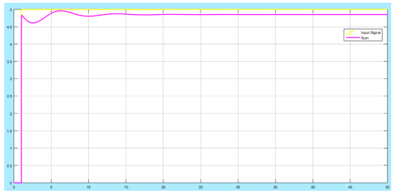
Figure 14: Plot of the system with feedback and feed-forward Kp = 5
In the feedback system above, the error signal is compared to the input signal and the error subtracted. The corrected signal is fed to the process (Singh and Agnihotri, 2001). The input signal is also fed to the feed-forward controller with a gain of 5. The output of the system is shown by the pink curve while the input signal is shown by the yellow curve.
The effect of the feedback in the system is reducing the error between the input step and the output. The rise of the output voltage at the first instance remains high, but the error in the signal is reduced to be almost equal to the input. In the diagram above, it is seen that the rise of the output signal is lower than the input step. In addition, the input signal has some oscillations before it stabilises after about 20 seconds. It is evident that including a feedback mechanism in signal analysis reduces the large error between the input and the output. The corrected signal is also fed to the feed-forward controller to adjust the hydrogen ions to bring it to a stable proportion of effective current production. The subsequent simulation will try to ensure there is little or no oscillations in the output by damping the system. In addition, the response time of the output signal has to be reduced.
For the control system design, a PID system is selected to ensure the higher order systems are effectively controlled. The proportional control is always effective for control systems of first-order whose disturbance is linear hence using a proportional control brings the system to stability. The combination of the PI controller is used for higher order nonlinear systems. It improves the accuracy of the system, but decreases the response speed and deteriorates the system’s stability. PID controllers are used for higher order non-linear systems that require improved stability. The derivative gain increases the response speed and improves the system’s accuracy. The simulation of the control system is done stepwise implementing the Ki, Kp and Kd respectively while the system’s response monitored.
PID feedback system Kp = 3, Ki = 0, Kd = 0
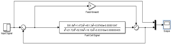
Figure 15: Proportional feedback control, Kp = 3
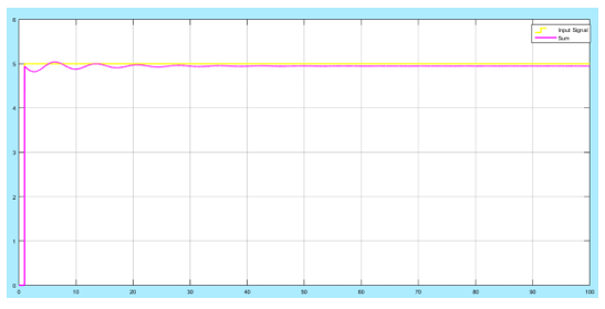
Figure 16: Output feedback response with Kp = 3
In the figure above, the error between the output signal and the input signal has reduced. It evident that Kp reduced the error in the signal proportionally. However, the stability is compromised. The output curve has more oscillations even beyond 50 seconds. When the signal was magnified, it had the response curve as shown in the figure below:
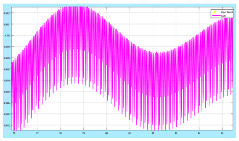
Figure 17: Magnification of the output signal to show its instability
The signal error is reduced, but its instability is increased. The frequency of oscillations about a point is high, these ought to be reduced to stabilize the fuel cell system. The integral controller was introduced to improve the accuracy of the system.
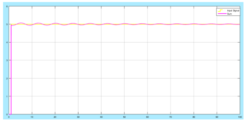
Figure 18: System output response with Kp = 3, Ki = 5
When Ki is included in the system, the response time of the output signal is reduced to a smaller margin. The oscillations on the output have the same frequency too, but their amplitude is reduced. It has improved the accuracy of the system by making the output equal to the input of the signal even though there are oscillations about the input.
The figure below gives a closer look at the oscillations of the signal about the step input:
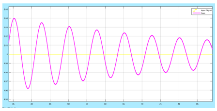
Figure 19: Oscillations of the output about the input signal
To increase the stability of the system, the Kd value has to be adjusted. The introduction of Kd increases the speed of response of the system and improves the stability, it has no impact on the accuracy of the system. To come up with an efficient response, the PID tuning tool is used. The response of the system to the PID tuning is shown below:
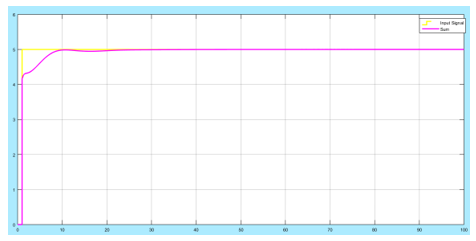
Figure 20: The response of the system to PID tuning; Kp = 0.198023, Ki = 0.047418, Kd = -0.421937
In the response above, the oscillations in the system after it settles are removed. The curve of the output is smoothed and stabilises after approximately 30 seconds. This means the PID control stabilises the system effectively and the output made to coincide with the required step input.
The feed-forward control can be tuned further to ensure the error between the step and the output at the step impulse is reduced. The difference indicates that at the start of operation of the fuel cell, the hydrogen ion concentration is lower than expected before the feedback system corrects the other influencing outputs to bring the hydrogen level to the required operating points.
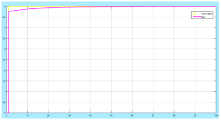
Figure 21: The output of the system with feed-forward gain reduced to Kp = 20
In the figure above, the error in the output and the input at the 5th second step has been lowered further. The disadvantage of increasing the Kp gain is introducing some oscillations in the output curve, such that the settling time of the curve is delayed further. The control system designer has to come up with the correct control gains to achieve the desired output. Using a Kp gain of lower than 1 for the feed-forward control leads to higher instability since the revel of hydrogen ions becomes unbalanced. The figure below illustrates the point when a feed-forward Kp gain of 0.5 is used.
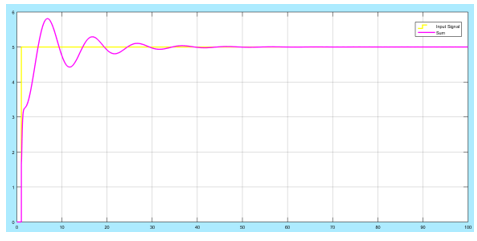
Figure 22: System with feed-forward Kp = 0.5
The lower the feed-forward Kp gain, the higher the amplitude of oscillations. The right value of the gain has to be selected for the real system.
5.3. Comparison of the signal without any control to the control achieved:
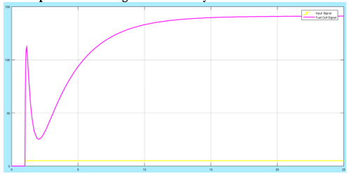
Figure 23: Signals without any control systems
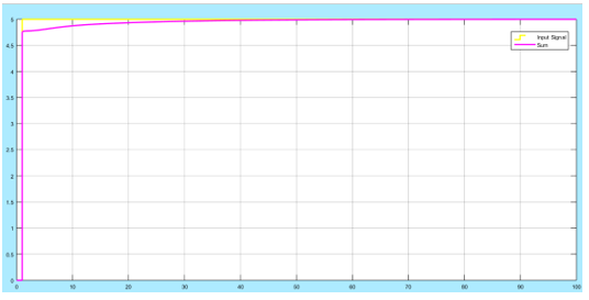
Figure 24: the controlled signal; feed-forward Kp = 20; Feedback Kp = 0.198023, Ki = 0.047418, Kd = -0.421937
From the two figures (figure 23 and figure 24), control is achieved to increase the accuracy of the system since the error is eliminated, the signal is stabilised and also the response time is reduced, its settling time is approximately 30 seconds. This is effective for a PEMFC.
CHAPTER 6: POTENTIAL CLIENTS
Fuel cells have wide industrial applications. Apart from being used as power supply systems in stationary applications in buildings, they are also effectively used in automobiles, in micro-grids and hybrid systems. Their use as a stand-alone stationary power supply in buildings has gained many advantages over the recent past since it provides clean energy with less noise. Their increased use of automobiles is because they are small in size, light in weight and have higher power output (Ulsoy, Peng and Çakmakci, 2012). They do not need recharging systems and are more durable. Their use in micro-grids is limited since ample tests have not been done on the reliability of the system in a large micro-grid in addition to the high capital investment needed. However, they are effectively used in hybrid systems together with other clean energy sources like the wind turbine energy and the solar energy. In this section, some of the potential clients for the PEMFC fuel cell are assessed and the benefit they would get if they implemented it in their plans. The best way to reach potential clients is to partner with the manufacturers who understand the industry and can make customised products for the market. Some of the clients identified are highlighted and discussed below.
Following are some of the companies, which can be potential clients of the ongoing project:
- Ballard Power Systems
They are the key player in the PEMFC market. Their product ranges from PEMFC stacks for transportation to single PEMFC for small electronic devices.
- Doosan Fuel Cell America:
They are fuel cell manufacturer with a major focus on the stationary fuel cell.
- Bloom Energy (Sunnyvale, California):
Though at present their focus is on solid oxide fuel cell (SOFC) major improvements in PEMFC control can also make them a potential client.
1.1. Ballard Power Systems:
Ballard Power Systems provides technology solutions by offering optimised fuel cell products for each industry. Some of the industry the company provides fuel cells are the defence industry. They cells provides are used to give the defence forces electrical power in locations where there is no connection to the national grid or in remote locations where there is no power source. The fuel cells provide more flexibility, utility and portability unlike the solar systems or wind energy for the military applications (Ballard, 2002). Therefore, having the right set of fuel cells will ensure the military personnel effectively carry out their tasks irrespective of their location.
Fuel cells also provide power to critical infrastructure especially in the construction phase where there can be no commissioned power supply to the site. For instance, during the project inceptions in the construction of buildings and other infrastructure, using power from the national grid may not be certified or other construction processes hinder the use of power from the main national grid. In addition, critical communication infrastructure may be located in regions that are uneconomical to supply power through cabling. For example, powering the communication repeaters and boosters located in mountains or densely forested areas. The fuel cells provide an ambient power supply to such critical communication infrastructure (Ballard, 2016). Other critical infrastructures include devices of systems that need an uninterrupted power supply like the airport radars. The system can be coupled with redundant fuel cells so that the systems will be powered in all seasons.
Due to its lightweight, portability and small in size, PEMFCs are best for the UAV. The drones use batteries but this limits their range. Batteries need recharging after a period of operation, this limits the time in the air from the UAVs. However, Ballard Power Systems manufactures fuel cells that have the right power requirements to power the UAVs for sustainable long flights. This will make them achieve the functions effectively.
Other common industries that Ballard Power Systems makes its fuel cells for is the rail industry, the automotive industry and the material handling industry (fuel cell powered forklifts for warehouse operations). Therefore, coming up with an effective PEMFC control system will enable the company to consider is an application to its ever-increasing demand.
1.2. Doosan Fuel Cell America
Doosan Fuel Cell America manufactures fuel cells for powering micro-grids and energy use for buildings. Apart from providing electrical power to buildings, the fuel cell sued in this case is also used for air conditioning. They provide heating and cooling solutions. Doosan America focuses on stationary fuel cells to power the buildings, unlike Ballard that diversifies its products for the portable applications. Some of the common application of the fuel cells from Doosan are industrial use, healthcare power solutions, power for data centres and telecommunication systems, commercial mixed-use and power for education facilities. The design and manufacture of these fuel cells will depend on power requirements tailored after feasibility studies are conducted. One of the greatest achievements of Doosan was the contract to provide 70 power units to Korea (Doosan, 2015). In 2017, it achieved a milestone of constructing Korea’s largest fuel cell production facility.
1.3. Bloom Energy
The company focuses on manufacturing solid oxide fuel cells (SOFCs), however, diversification to better-controlled fuel cells is an opportunity they can grab for to increase its product portfolio. The company provides onsite power generation systems, it has manufactured fuel cell for use in the NASA. The company’s systems have effectively provided electrical power that significantly reduced the electricity costs for the users. The use of its power solutions provides reliability and energy security.
The company can implement the PEM fuel cells with better control as compared to the solid oxide fuel cells. The SOFC produce relatively higher heat in their operation hence it is challenging to manufacture the components that withstand the high heat of operation and still maintain optimum power supply. The high heat emission leads to energy losses in form of heat. The performance of SOFCs deteriorates over time, the use of PEMFC is reliable for longer durations of operation. The cost of fabrication of SOFCs is higher due to the materials used to make the fuel cell to withstand the higher heat from the electricity production process. On the other hand, the PEMFCs produce less heat in the electricity production process, leading to fewer energy losses in form of heat. The material to manufacture the stacks is less costly hence it generally has a lower capital investment. In case Bloom Energy switches to the PEMFCs, it will increase the efficiency of its solutions and maintain the market leadership.
Other companies that can embrace the PEMFCs are SFC energy for mobile energy solutions and power management in the industry. ACAL deals with manufacturing and distributing customer-specific components to worldwide companies. The diversified fields include transportation, communication, industrial, renewable energy and defence sectors. The use of fully controlled fuel cells will offer the best applications to its consumers. ACUMENTRICS manufactures for prime defence contractors, Aisin Seiki Company in Japan manufactures fuel cells for the automotive industry and Delphi Automotive Systems that manufactures cells for the automotive sector. All these are the potential clients for the fuel cell, they reach out to diversified industrial applications worldwide.
CHAPTER 7: CONCLUSION
The objective of the study was to come up with the control system of a fuel cell. The control system to be implemented was the feed-forward and the feedback control. This was to be implemented in MATLAB &SIMULINK, the simulations carried out would assess the effect of the control system to the output. The findings and discussion of the system were made to obtain a greater understanding of the operation of the system. This was successfully done and the project objectives achieved. In addition, the potential clients of the system were identified and the effective system compared with the current systems manufactured by the clients.
Fuel cells work by changing the chemical energy of the reactants to electrical energy. This is by the redox reaction. Hydrogen is oxidised at the anode, it loses an electron to become a proton. The electron travels through the conductor to the cathode to generate an electrical current in the conductor. The proton exchange membrane used is the Nafion 117. At the cathode side, air (oxygen) is allowed into the system, it is reduced by gaining an electron to form an oxygen ion. The hydrogen ion and the oxygen ion combine to form water as the by-product of the process. The water recycled into the system since it humidifies the inputs and the membrane for optimum power production. The system, therefore, needs optimum temperature and the correct ratio of the reactants to achieve the desired electrical power levels.
There are always many disturbances in the system which are the fluctuation of the hydrogen ion concentration, fluctuation in the temperature levels, fluctuation in the ratio of the inputs, and the fluctuation in the humidification process. The major disturbance in the system is the fluctuation of the hydrogen ion levels, the consequence is unstable power production of the system that may cause short-circuiting to the load. A control system that anticipates the level of hydrogen ions is needed to control this in the fuel cell (Wang, 2008). A feed-forward controller was designed to regulate the level of hydrogen ions. This goes back to the control of the compressor valve to limit the hydrogen gas mass flow rate into the system. The operating conditions in the cell like the temperature are best regulated by a feedback system.
The temperature is regulated by the heating and cooling system, in case lower temperatures are needed the system will activate the fan. The fuel-air ratio is thus dependent on the concentration of hydrogen ions, higher levels of hydrogen ions will make the feedback system increase the mass flow rate of oxygen into the system. Besides this, in order to start a PEMFC stack after a long time, it is required to carry out purging of stored oxygen which is seeped into the anode from ambient. It is also required to mix leftover hydrogen gas from last operating cycle. If this is left uncontrolled, it can result in the very high voltage at the start-up of the stack and can ultimately result in quick degradation of anodes. Humidification of the electrons is also important for optimum power production, the feedback system will, therefore, control the level of humidification to get the required power levels. The feedback processes were controlled by a PID control since the parameters are higher-order non-linear systems. Due to the complexity in integrating the system, the transfer function from previous research by Subhasree1 and Kotteswaran (2006, p.3) was used in modelling.
In the design of the controllers, the feed-forward and feedback output response were simulated in MATLAB to achieve the desired output levels in the control process. The simulation was successfully done to ensure a stable output, with high accuracy and a short response time. The challenge in the design was to find the right match of the Kp, Ki, and Kd gain values for the PID controller together with the Kp values for the feed-forward controller. The PID tuning tool was used to find the right values for the feedback control system, however, integrating the feedback and the feed-forward to a perfect control unit was not optimized. It was only done to a satisfactory level, there is still room for improvement. More work needs to be done in this area to get a perfect control unit that enables better control and efficiency.
RECOMMENDATIONS
The recommendations for the fuel cell controls system are that the design parameter should be known prior to the project so that a bespoke control system can be designed to suit the cell specifications. For example, the voltage and current characteristics should be known, together with characteristics of the load, for example, its resistance. When these essential characteristics are defined, it is easier to work back to calculate the mass flow rates of the hydrogen and oxygen to be allowed to the system, the temperature levels required, the humidification levels required the rate of removing the by-products from the system etc. this makes it simple to model the transfer function for the system since the parameters are known. Since these parameters were not given at the beginning of the project, a control transfer function from a previous study was just selected to be modelled. A more specific approach should be adopted to make the system more applicable to the industry or to meet a certain design requirement. To achieve a more specific approach, the potential clients can be involved, so that the challenges they face in their innovated systems can be selected as projects for the students to work on. It will improve the application of the project to the industry since it will meet the specific need.
The use of fuel cells is currently limited because the initial cost of manufacture is high, making the costs to acquire it rather high too. Even though the initial investment is high, the long-term savings and benefits far outweigh the initial costs (Daud et al, 2017). They do not only serve as backup sources of electrical power but can be relied on as sustainable electrical power sources. The efficiency of the fuel cells depends on the type, the selection will depend on the power requirements. Higher efficiency fuel cells are more costly but they provide better power reliability. The research into microbial fuel cells provides a promising source of power. They use waste water, organic matter to produce electrical power. These greener sources of energy that is much cheaper to invest in. The focus for future projects should focus on the microbial fuel cells since the input raw materials are more available, this will reduce their costs.
CRITICAL EVALUATION
The work was successfully done, the project objectives were achieved because the control system of the fuel cell was designed and simulated in MATLAB. Both the feed-forward and feedback control were successfully simulated and their response to the control discussed. The areas of improvement identified are designing a system to meet a particular industrial need or gap. This is done by having the parameters of operation of the particular fuel cell and working to achieve a bespoke solution. This will give way for better efficiency for subsequent research and provide students with industry-linked skills to solve particular solutions.
If given a chance to work on the project again, I would work on fabricating the system. This is because theoretical analysis gives the ideal response of the system. However, fabricating the system will assess its actual performance and give a chance in improving the system. Finding the difference between the actual performance and ideal performance assess the losses in the system or other factors not considered in the design for correction.