


Chapter 1: Introduction
1.1. Introduction:
In the last few decades, there has been a rapid growth in the mobility sector across the world. A majority of these developments belong to road transportation. But this growth has also resulted in the drastic increase in traffic congestion, a number of road accidents and exhaust emissions. To improve the conventional road transportation, one of the most promising developments in last few years is the field of autonomous vehicles (Fossen et al, 2017). The first and foremost challenge an autonomous vehicle needs to overcome is to avoid collision with any static or dynamic obstacle along its path of motion. This signifies that autonomous vehicles should possess the capabilities of performing emergency manoeuvres in case it detects any obstacle. To avoid any static or dynamic obstacle on the path of autonomous vehicle it has to either decelerate to complete stop on the same lane or to manoeuvre to the neighbouring lane based on the traffic flow of that lane (Brandt et al, 2005). This project is intended to design and simulate a vehicle avoidance system for an autonomous vehicle not only to avoid collision and maintain stability of the vehicle but also to maintain traffic flow.
1.2. Aim & Objectives:
The aim of this project is to propose and simulate a collision avoidance system for autonomous vehicles to avoid static or dynamic obstacles.
Following are the project objectives:
- To understand the concept of autonomous vehicles and associated technologies
- To investigate the available technologies for collision avoidance and their advantages, potential and limitations
- To develop a dynamic model of an autonomous vehicle and design suitable trajectories to be followed by the vehicles
- To design a controller to implement suitable strategies in order to avoid collision by an autonomous vehicle
- To implement the controller along with vehicle model in Matlab/ Simulink and validate the design against requirements
1.3. Research Questions:
The following research questions are needed to be answered through the course of this project:
- What are technologies available for an autonomous vehicle to avoid collision on the road?
- What are possible sources of improvements of the existing technologies?
- What are different sources of obstacles in the way of a vehicle and what are the physical solutions to avoid collision with those obstacles?
- How to implement a controller and incorporate intelligence into the vehicle to take decisions as soon as there is an obstacle is detected?
1.4. Rationale:
One of the most common technologies adopted in autonomous vehicles is the Adaptive Cruise Control (ACC). In this technology, either a lidar sensor or a frontal radar is used to detect any obstacle in front of the vehicle. Then based on this information speed of the vehicle is automatically adjusted to keep the vehicle at a safe prefixed distance from the static or moving object (Kim et al, 2009). To avoid collision a vehicle needs to perform either of the two operations: deceleration of the vehicle to full stop before the obstacle or execution of manoeuvre to change the lane timely. The second option of changing the lane is more suitable for road transportation because traffic flow is least disturbed due to lesser deceleration. In ACC deceleration of the vehicle is possible only in the same lane. Hence there is a requirement of more agile technology for autonomous vehicles to avoid collision while maintaining smooth traffic flow (Jurgen, 2017).
In lane changing manoeuvre for autonomous vehicles, it is utmost importance to analyse the traffic flow in the surrounding lanes as well. The technology should be able to analyse information related to the speed of vehicles, distance from the obstacle, traffic condition simultaneously. The technology should be robust enough to take decisions on whether to change lane to avoid collision or to stay in the same lane with deceleration (Durali et al, 2006).
1.5. Brief Literature Review:
The most expected technological capabilities of an autonomous vehicle are obstacle avoidance, lane change, lane keeping and road following. For lane keeping as well as road following there have been extensive experimental and theoretical works carried out by researchers around the world. There are also several types of research on the manoeuvre for lane changes as well. In comparison, there is still scope for improvements in the field of automated manoeuvres for collision avoidance (Adouane, 2015).
In some of the research, obstacle on the path of the autonomous vehicle is interpreted as an electric field by interpreting the vehicle as electric charge in that field. The trajectory of the vehicle is determined by the forces applied to the electric charge. On the other hand, elastic band theory is also approximated in order to propose automated collision avoidance system by some other researchers. Elastic bands or nodes connected through springs are used in this approach to determine the desired trajectory of the vehicle. Force is applied to the nodes by the obstacles. From the obstacles, elastic bands are repelled by these externally applied forces. This, in turn, generates a desirable trajectory for the autonomous vehicles (Cheng, 2011). But this approach has limitations in real-time implementation due to the presence of non-linear equations. There are also optimization-based methods for overtaking a slower-moving vehicle using the optimal trajectory. But this solution is also not suitable for real-time implementation. Hence approximating the optimal trajectory through closed-form equations is considered as a viable option to implement collision avoidance system in real-time (Durali et al, 2006).
1.6. Project Outline:
Following the structure of the followed for the rest of the project:
Chapter 2: This chapter will provide a detailed literature review on different existing technologies for collision avoidance system. This chapter will bring out the generic layout followed in this system for autonomous vehicles. In addition, brings out the general impact of road accidents due to collisions with obstacles, gives a brief history of the progress made in the collision avoidance system and the subsystems modelled.
Chapter 3: this has the project plan outlining the activities to be done at each step of the project accomplishment. It also gives the Gantt chart detailing the project tasks at every stage of work.
Chapter 4: This chapter explains the code developed for the sensors. A detailed mathematical model of dynamic autonomous vehicle will be presented in this chapter. This chapter will also design number of trajectories to be followed by the vehicle. A number of controllers will be investigated and the optimum controller for the system will be selected. In this chapter too, the process of implementation of the proposed model in Matlab will be discussed. Results of simulation will be presented through plots and graphics. Findings of the Matlab simulation as well as literature review will be discussed in detail in this chapter. This chapter will also evaluate whether the proposed model is suitable to avoid collision or not.
Chapter 5: This chapter covers the mathematical modelling of the yawing system to come up with the transfer function for the vehicle. The MATLAB model for the system is then used to analyse the transfer function developed. It goes to the extent of designing the PID control for the system to ensure the appropriate control mechanism is effected in the system.
Chapter 6: Discussion and Findings: This chapter covers the findings in the code implemented and the control system. The effect of the controllers on the transfer function and is discussed. In addition, the comments on the usability of the code and model developed are highlighted. It also covers the benefits of the system to the automobile industry and other applications outside the automobile industry.
Chapter 7: Potential Clients: this chapter covers the potential clients of the system. These are the automobile industry, the aircraft industry, making collision avoidance white sticks for blind people and other considered applications.
Chapter 8: Conclusion and Recommendations: This chapter covers the conclusion of the project. It discusses the challenges and the recommendations for future research and projects.
APPENDIX: This part contains all the MATLAB code along with functions being used in modelling the sensor system to avoid collision with the obstacles along its trajectory as it moves from one point to its destination. The code has comments to make it easily understood.
Chapter 2: Literature Review
2.1. Overview of Intelligent Transport System (ITS):
Across the world, there has been a drastic rise in the number of fatalities and damages due to road accidents in last few decades, there have been substantial researches carried out to improve road safety. All these research are generally included in the generic term of ITS or Intelligent Transport Systems. These alternative technologies integrate the collection of information from other vehicles or from cloud and servers, processing of relevant information and taking control decision autonomously. All these technologies have the fundamental goals of reducing the number of on-road accidents, saving energy, reduction of pollutant emission and improvement in transport system efficiency (Cheng, 2011).
Broadly the vehicle safety systems are categorized into active and passive safety. Reduction in the number of accidents is the aim of active safety system whereas the reduction in accidental consequences is the aim of the passive safety system. But in more elaborative studies these are more commonly classified into primary and secondary safety systems (Fazlollahtabar, 2016). Pre-collision safety system and driver assistance system in these studies are categorized as a tertiary safety system. In these tertiary systems number of sensors are used in the vehicle in order to collect relevant information about traffic flow, distance from other vehicle or any obstacle, the velocity of the front and rear vehicles etc. This information are processed and forwarded to controller and protection systems for reducing probabilities as well as consequences of accidents (Falcone et al, 2007). The tertiary technologies are designed to take advance measures in order to allow other measures to be adopted or to increase the effectiveness of new measures. Some critical measures to be taken are automated changing in steering angle, automated braking, preparing airbag for any probable collision, activation of pre-tensioner etc. There are also some advanced measures such as control of suspension height, use of extendable bumpers, measures for minimization of pedestrian accidents etc. adopted for improving inter-vehicle compatibility (Carvalho et al, 2013).
2.2. Overview of Existing Collision Avoidance System:
All these safety systems comprise of two major aspects such as detection and interpretation of vehicle surroundings and decisions for taking corrective measures. The first aspect must be capable of processing information and decide whether the identified obstacle is a real or potential obstacle along the vehicle path or not. There are different technologies adopted in autonomous vehicles such as laser scanner, radar, computer vision for detection of vehicle surroundings in the long range. Each sensor has their own advantages and limitations. Therefore in more recent autonomous vehicles fusion of different sensors is used for enhancing the possibilities to understand and represent the vehicle surroundings. In order to achieve sensor fusion numerous complicated algorithms are developed so far by researchers (Jurgen, 2017).
In detection and tracking of obstacles there are extensive research projects carried out around the world to develop algorithms to make use of sensor supplied information and integration in the control system. Researchers have presented a collision avoidance system based on stereovision system. This system is used to detect pedestrians through algorithms used for detecting and tracking pedestrian. Based on the movement of the pedestrian, this algorithm is capable of predicting whether the pedestrian will come in the path of the vehicle or not. In case of any potential collision with the pedestrian suitable actions are taken by the system either to deviate or to stop the vehicle. In GPS-based autonomous vehicles this sensor fusion based collision avoidance system is already implemented by researchers (Dhivya et al, 2015).
In simulation environment there have been numerous complex controllers along with vehicle dynamic models are implemented. But these systems are extremely non-linear and complicated to be implemented in real-time on autonomous vehicles. More recently usage of digital maps for navigation of autonomous vehicles has gain lot of popularity. In these maps obstacles can be positioned at different location and these information can be directly communicated to GPS navigation (Riaz et al, 2012).
The next critical aspect in any collision avoidance system is to take necessary decision or measures to avoid collision with the detected obstacle. In autonomous vehicles the most common practice in this aspect is to correct the steering angle and apply required braking to avoid collision either by diverting or by slowing down or by completely stopping the car. In this aspect implementation of more and more artificial intelligence (AI) is in progress in autonomous vehicles. AI is used for automated management of actuator and controller for enabling collision avoidance system and driver assistance system (Sotelo, 2003).
Some researchers have presented pre-collision group of systems for collision avoidance based on identification of obstacle. These are mostly implemented for avoiding collision with pedestrians and theoretically overtaking vehicles moving slowly in front of the autonomous vehicle. It is to be ensured that in order to implement corrective measures for preventing or reducing possibilities of collision sufficient information are available through the local sensors placed on the autonomous vehicles (Verma, 2014).
Autonomous vehicles also need to collect traffic flow information based on the communication with other vehicles as well as information collected from cloud. From the vehicle surroundings Advanced Driver Assistance Systems (ADAS) collects required information through Vehicle-to-Infrastructure (V2I) and Vehicle-to-Vehicle (V2V) communications (Adouane, 2015).
At present there are in general two broad classes of safety systems as cooperative systems and autonomous systems. Intra-vehicle communications form the basis for cooperative systems whereas local sensors form the basis for autonomous systems. All the communication systems intend to observe the horizon of the vehicle thereby providing sufficient time for the vehicle to adapt corrective measures. Autonomous vehicles not only receive information from vehicles and infrastructure but also transmit required information to infrastructure and other surrounding vehicles. Therefore there is a two-way communication established in all the autonomous vehicles (Durali et al, 2006).
2.3. General Layout of Collision Avoidance System:
There are in general four different modules consisted in any Collision Avoidance System for autonomous vehicles:
- Obstacle detection module:
This particular module is used for detecting and tracking obstacles and determining direction as well as speed in order to differentiate obstacles whether it will fall within the trajectory of the autonomous vehicle or not. Accurate positioning of obstacle as well as vehicles on the digital maps is more useful as recommended by researchers to provide additional information (Jiménez, 2012).
- Decision making module:
Based on the information from vehicle surroundings for avoiding an accident or for minimizing the accidental consequences required actions are taken by this module. It is also to be ensured that corrective measures do not initiate any risks for other vehicles on road. Information related to characteristics of road, movement of the vehicle, traffic flow, movement of surrounding vehicles etc. are processed in this module. This module generates required feasible manoeuvres to avoid collision with the obstacles (Cheng, 2011).
- Autonomous manoeuvring module:
Controls of the autonomous vehicle such as brake pedal, steering angle etc. are actuated by this module as per the output of decision module. This in turn generates required manoeuvres of the autonomous vehicle to avoid collision.
- Communication module:
Required information are received as well as transmitted by this module of autonomous vehicle’s collision avoidance system .These information are communicated both to nearby vehicles and to the cloud. This communication warns the surrounding vehicles about the possible manoeuvres the autonomous vehicle can take and allow the surrounding vehicle sufficient time to take action if required (Jiménez, 2012).
2.4. Automotive Safety:
The most important issues from the last few decades are the safety and security of the passengers in case of car driving. From the last few decades crashworthiness of automobile has upgraded excessively. The chance of disastrous injury in a new car has been lowered by 90% in comparison to an old car of early 80’s.From the analysis of results of various crash examinations implemented through the various worldwide organizations; the proof of crash performance has been upgraded. Though there is an improvement yet there are many people who have been injured or killed in road traffic accidents. As par one database recording report of all destructive car accidents so called FARS report, in USA, for the year of 2000, a total of 37409 accidents has taken place. In which all total 41821 people has been reported dead. The total number of non-lethal accidents and non-fatal injuries of the year 2000 are much more than the reported fatal one. In spite of modern new cars’ upgraded crashworthiness also there is a significant necessity in case of reduction of injury caused by traffic road accidents. As per necessity the technologies behind passive safety has been upgraded much more (Durali et al, 2006).
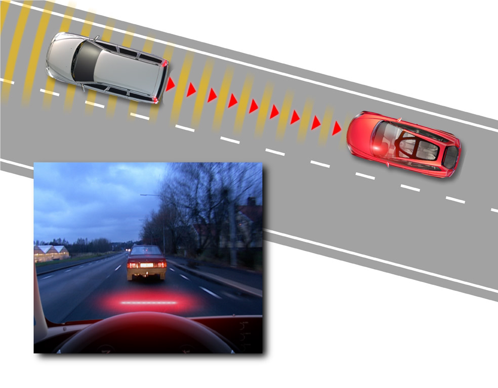
Figure 1. A collision mitigation (CM) system’s example (Jansson, 2018)
Here the collision mitigation (CM) system utilizes radar in case of measurement of distance and relative speed with respect to the motor vehicle ahead. This system alerts the driver by giving a projection of flash of red light above the windshield in case of collision emergency. That is why, the injuries and accidents has been decreased significantly by these technologies behind passive safety. Due to this non-expensive technology these type of accidents become impossible. In present years, automotive industry’s people also have raised their efficiencies for the determination of other technologies and way out for the decline number of injured people in traffic road accidents (Jansson, 2018).
Alternative ways to avoid accidents: With the help of driver support systems the occurrence of accidents can be prevented.
- ABS or the anti-blockier system, braking system is the example of the driver support systems which is necessary for a driver in case of steerability management for hard braking movement.
- The yaw control is another safety system which has been established itself very useful in case of reduction of chances of injury. With respect to the condition of road, this system has been utilized in case of reduction of chances of injury by up to 50% (Jurgen, 2017).
- The CM system utilizes the sensors for monitoring the direct circumstances in front of the host motor car. As par the data received from the forward-looking sensors a conclusion can be taken place regarding the use of countermeasures to prevent inevitable face to face accident.
Normal caution technologies can be through visible, audible or haptic/tactile warning signals or can be through steering system or braking system (Falcone et al, 2007).
An example of CM System is shown in Fig.1. This system cautions driver regarding inevitable collision by the demonstration of a visible output. Though passive security and safety are the main concern topic for many people in case of safety and security for car yet in case of modern motor vehicle many more other things have to be studied. For increasing the safety and security of the passenger as well as the driver, the modern systems like yaw control, ABS brakes etc. has been launched. Those are usually known as active safety and security systems also.
In other way the motor vehicle which has the quality of good active safety and security should possesses the quality of good maintaining ability. In next section different views regarding the safety and security of motor vehicle has been discussed (Riaz et al, 2012).
In wider point of view there are three sections, by combining those, total discussion regarding the safety and security properties of a motor vehicle can be completed. Those are:
- Passive safety
- Active safety
- Security
Security section will not be demonstrated in detail in this report. The detail discussion regarding passive and active safety will be here in the next sections (Riaz et al, 2012).
2.4.1. Passive Safety:
Passive safety of a car is basically the capability of a car or motor vehicle to safeguard the passengers from the damage in an accident. This capability to safeguard the passenger from any injuries in an accident is frequently known as the crashworthiness of the vehicle. In this demonstration, the passive safety and security properties of a motor vehicle or the crashworthiness of a motor vehicle has been mentioned as a capability to safeguard the passengers from any type of damage in case of pre and post inevitable circumstances of an accident. There are many different ways which can protect the passenger from any type of injuries in an accidental case (Cheng, 2011). Those are:
- Optimization of the vehicle’s structural body in such a way that can increase the vehicle’s crashworthiness or passive safety properties. In this case the consumption power of crash energy of the vehicle’s body will be such that the passengers will experience minimum level of instantaneous acceleration or crash pulse.
- Other systems such as airbags, seat belts, belt load limiters and belt pre-tensioners etc. also give protection to the passengers in case of an accident.
- The interior design of a motor vehicle specifically the switches, the panels etc. should be introduced in such a pattern that it decreases the chances of any type of injury (Brandt et al, 2005).
The motor vehicle’s design with respect to certain areas has to be examined thoroughly for enhancing the good safety and security properties of the vehicle. In case of examinations of accidents the crashworthiness of the vehicles should always be examined first.
ANCAP, EuroNCAP, NHTSA and JNCAP are the organizations which are initiating those examination regarding crashworthiness of vehicles. These organizations here initiating the test in a proper way and here the passive safety and security properties have been calculated with the measurement of forces and accelerations observed by creating a certain duplicate accidental circumstances. IIHS and Folksam are some insurance organizations which also measured the automobiles’ crashworthiness. These institutes actually certify the proper capability of various automobiles with respect to the cases of actual life collisions (Dhivya et al, 2015).
2.4.2. Active Safety:
Just like passive safety and security, active safety consists of various visible features of the motor vehicle and that active safety property can be segregated into three various sections. Those are: preventive, dynamic and collision reduction. The illustrations of these sections are demonstrated here.
- Preventive —there are many features involved in case of the preventive type of active safety and security property. These features involved are:
- The observation of danger by the driver.
- The early detection of danger will help the driver in case of taking precautions from an inevitable accident. (Jansson, 2018)
Several aspects in this regard will give the proper understanding. Those are:
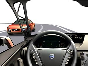
Figure 2. Preventive active safety and security technology in a Volvo car (Jansson, 2018)
- Danger detection:
In a conventional way by increasing the headlight efficiency, clean and clear headlight and windshield, windows’ minimum possible glare etc. the enhancement in case of the understanding capability of the driver is possible.
The systems for night vision and see-through A-pillars are the basic models of modern discoveries which help to increase the awareness power of the driver. An IR camera and a display unit for the driver are the basic parts of the systems for night vision which help the driver by producing an IR image for the better perception power of the driver. This technology, here help the driver in case of the detection of hot objects however far away than the usual one in a better possible manner through its traditional headlights. The utilization of night vision systems in case of automotive devices for automobiles will be discussed further (Jiménez et al, 2012).
In Fig.2, it is clearly depicted that a see-through pillar has been utilized to increase the understanding capability of the driver by deploying his or her view through the A-pillar in a case of Volvo Safety Concept-oriented Car (SCC).
- Visibility: In case of preventive active safety and security issue another vital aspect is visibility power of self-possessed car of the driver. The proper design of the vehicle should be in such a way that the each and every road user easily visualize it. High- positioned brake lights, daytime running lights are some examples of technologies which also increase the visibility power of vehicles (Jansson, 2018).
- Geographically-dependent road information to the driver:
Road information to the driver is again a vital aspect which helps the drivers in case of threat detection. Nowadays the digital maps as wells as GPS technology play an important role in providing the geographically-oriented knowledge to the driver. Monitoring systems for road friction as well as the monitoring systems for tire pressure measurements are the modern technologies which help the driver to prevent accidents by equipped him with some necessary information (Cheng, 2011). It is vital to recall the mental and emotional capability is somehow definite and more than data entry in the human brain can be the reason of failure in case of threat detection or can be the reason of wrong decision to inevitable danger. Nowadays the intelligent driver information system (IDIS) has been launched in case of Volvo V50 and Volvo S40 which can easily exhibit the important priority basis data to the driver as per the demand on the circumstances (Fossen et al, 2017).
- The driver Monitoring System:
Sometimes driver monitoring system also may be required for increasing the understanding capability of the driver in case of sufficient traffic rule oriented circumstances. This type of system can give the caution signal to the driver whenever he feels sleepy or drowsy in driver’s seat (Cheng, 2011).
- Dynamic:
As par the viewpoint of safety and security, a vehicle’s design should be such that it can be safely handled. The vehicle’s model should be such that the driver’s control over the vehicle in all possible bad road circumstances as well as in various types of traffic situations during different types of manoeuvres should be good enough for avoiding any collision.
Here some examples are discussed:
- The vehicle’s design should be such that the dynamic driven characteristics should be proper enough for easy movement in any direction without sacrificing the grip over the vehicle (Sotelo, 2003).
- The vehicle’s design should be such that there should be least minimum interference due to side wind. By the means, the car’s design should be such that the driver can maintain the car with his defined pathway easily. For achieving these characteristics, there should be some areas of the vehicle which has to be modified in case of car’s design. Vital areas are basically brake system properties and steering wheel.
Many active systems have been devised which can improve the dynamic characteristics of an automobile. These so-called “active systems” are basically the utilization of actuators and sensors which for getting improved performance of various closed loop which is really helpful for the driver in case of control of the car (Jansson, 2018).
- Collision Mitigation System:
Collision Mitigation system can supply various notions regarding the automobile’s environmental circumstances. On the basis of this point of view, the system can take various approaches by which inevitable accidents can be avoided (Jansson, 2018).
In this area only there is a chance to improve. That is why these systems are frequently known as Collision Mitigation system. The word mitigation has been used because with the help of these systems only accident can be avoided fully. Due to various logics the collision mitigation system which helps to mitigate the accidents are really inaccessible in case of utilisation for the vehicle. Normally with the help of CM system collisions’ harshness can be reduced up to some extent in the presence of restraints. As par best possible scenario, the collision can be mitigated with all positive effects of CM system, on the other hand, in the worst case scenario this CM system may not help at all. There are many systems which have CM system’s properties (Brandt et al, 2005). Those are:
- One of these systems is Lane-keeping aid system which helps to observe the lines marked in a road. With the help of this road marking monitoring capability, the position of the automobile in the road can easily be estimated. If the car is skid out from the road then one caution signal may be given or some interference regarding the steering wheel may happen.
- Another system with CM functionality is forward collision mitigation system, which has the power to observe the presence of any vehicle before the host vehicle and creates interventions to mitigate a face to face accident (Carvalho et al, 2013).
- Just like a normal cruise control, another system with CM functional ability is adaptive cruise control which easily can adjust with the velocity of the vehicle in front of the host vehicle whenever the driver is just nearby of that car on the same
- There is another CM system called Lane change aid system which observes the distances behind the vehicle as well as the blind spot This system produces interventions through the creation of some torques of the steering wheel to mitigate one accident in case of lane change (Kim et al, 2009).
2.4.3. Security:
The vehicle’s ability to prevent danger, threat and any type of destruction is the main aspect of security (Jansson, 2018).
2.5. Several types of accident:
CM systems applications in some cases are really restricted. It is really true that with the help of this CM system also not all types of collisions can be prevented. Some general cases of collisions where the applications of forward-looking CM systems are really inadequate are those in which the POV so-called principal other vehicle meets the host car from the side direction. That is why the POV’s appearance in the sensor’s field of view so-called FOV is actually very late or sometimes absent also. In Figure 3, it has been clearly depicted that there were many various types of collisions happened in the USA in 1998 which are rather common (Verma, 2014).
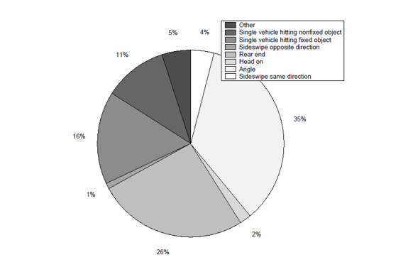
Figure 3. Various common types of collisions in the USA in 1998 depicted through pi-chart (GES, 2002)
This statistical diagram is based on a specific database that is called GES database. Rear-end accidents’ percentage is 26 % through the CM system with forward-looking properties. Another type of accident caused by forward-looking CM system is static single automobile hit with 16 % probability. The accident probability due to one forward-looking system such as non-static vehicle collisions is 11 %. The main analysis regarding these types of accident is the possession of stuck vehicle’s view in the field of the viewpoint of the forward-looking CM system’s sensors for a more than a long period of time (more than seconds). With the basis of statistical data collections from single automobile collisions and rear-end collisions, it has been observed that the more than half percentage that is above 50 % of total collisions are due to this forward-looking CM system only. The most vital fact in case of the effectiveness of the active safety and security properties is the learning regarding the driver’s activity just before the collisions (GES, 2002).
Rear-end accidents again can be segregated into five different sections. It has been observed that the driver can’t take any precautionary manoeuvre such as with steering wheel or with brake system in case of more than 68% of collisions for these different five sections of rear-end accidents (Verma, 2014).
Chapter 3: Project Plan
3.1. Project Methodology:
This project is aimed at designing a system for an autonomous vehicle in order to avoid a collision on the path due to static or dynamic obstacles. At first, a detailed literature review of all the existing methodologies for collision avoidance in autonomous vehicles will be carried out. Literature can be relevant and recent journal publications, books on autonomous vehicles and navigation, conference proceedings and online articles. Based on the literature findings a mathematical model of the autonomous vehicle will be developed. A specific trajectory for the vehicle to be followed will be selected. Then suitable controllers will be investigated and the optimal controller will be finalized. Then the vehicle model along with the controller will be implemented using Matlab/ Simulink software. At the end, the proposed model will be validated whether it is able to avoid the collision or not through suitable strategies.
In the detailed literature review at first, different existing technologies for collision avoidance system will be investigated in detail. This analysis will include the working principles, associated principles along with the scope of the system. A generic layout of the collision avoidance system will be studied in order propose and design a new system. All these studies will bring out the requirements of the system.
In developing the mathematical model special attention will be provided to the problem formulation. It is to be confirmed that there are no non-linearity, optimization problem or any other complicated formulation which cannot be implemented in real-time.
In the software implementation of the model special attention will be provided to capture runtime of the model. This will ensure that the model is fast enough to take a required decision on time. Finally, the model will be evaluated based on specific test cases whether the vehicle is able to avoid collision in all these cases or not. Failure of a single test case will result in failure of the proposed model in avoiding collision.
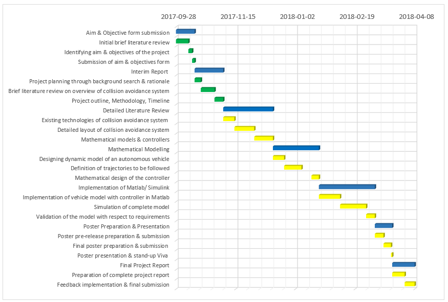
3.2. Gantt Chart:
The following timeline will be followed in this project:
Chapter 4: Modelling the Sensor System: Code Explanation
This chapter contains the complete description of MATLAB code for this assignment. Several functions have been used to implement the desired logic. In the main script, firstly a check is being used for the compatibility of OCTAVE version. Features like window coordinates, speed threshold, sensing radius and other attributes are set after several experimental iterations.
Now, to begin interfacing with the user, figure environment is set using the respective commands. The following figure shows the plot being shown on running the script. The black spot in the figure is the centre of the robot which is marked by the user randomly.
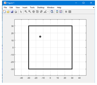
Figure 4. Robot centre point marked by the user
After setting the position of the robot, the goal point is set by the marker as shown below in the following figure.
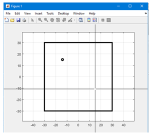
Figure 5. Goal marking for the destination of the robot
When the goal is set, several moving obstacles (threats) are generated. A number of threats is already defined by us in the code. Using random function, the positions and velocities of these threats are set randomly within some range. Then a forever loop is used for the movement of the robot. In the loop, the distance of the robot from the current position to the final destination is calculated by passing the respective coordinates in a function named ‘TakeSensorReading’. Robot moves following three different moving schemes. One is conicfield, other is quadraticfield and the last one is the combination of the first two.
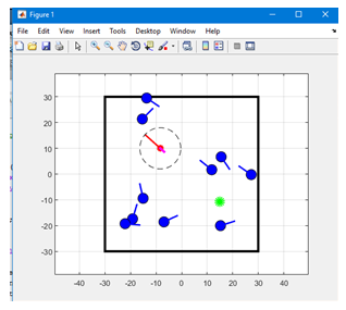
Figure 6. Robot movement towards the destination
Above figure shows the movement of robot towards the destination. The green coloured spot is the destination. Red coloured spot with circular lines is the robot. Threats are shown using blue colour. Each threat is then moved. If the threat is facing the wall, it is bounced back. Distance from threat makes the robot’s speed and direction vary accordingly. However, if a robot collides with the threat, a message is displayed. Similarly, upon reaching the destination, a message toast is displayed showing the successful movement of the robot. The following figure shows the working of the system explained.
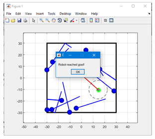
Figure 7. Path completion successful
The MATLAB code is attached in appendices with comments to make it understandable.
Chapter 5: Mathematical Modelling of the Yawing system
To avoid collision in the vehicles, they move either to the left or to the right to change lanes and avoid colliding with the obstacle. In cases where there is traffic congestion and the vehicle cannot change lanes, the vehicle has to slow down. The movement to the left or to the right of a moving object is referred to as yawing (Rosolia et al., 2015). It is characterized by the angle taken called the sideslip angle and the yawing angular velocity. In normal driving situations, the side slip angle is determined by the change in the steering angle to achieve the desired change in direction to avoid collision. When coming up with the model for achieving effective control, the vehicle parameters have to be determined, the characteristics of the road and other salient information that defines the movement of the vehicle to avoid collisions.
When coming up with the model of the vehicle, the major disturbance in the system is the instability of the vehicle when yawing (Han et al., 2017). The vehicle should avoid collision with objects without losing control and rolling off the road to cause accidents and fertilities. The implementation of the effective and efficient yawing mechanism is meant to ensure the vehicle does not roll in case it avoids the collision. The design process will, therefore, consider the vehicle characteristics, the speed, the friction on the road surface, the weight and momentum of the vehicle to determine the optimum conditions to avoid losing stability and rolling off the road (Khairnar, Phalle and Mantha, 2015). The modelling takes a step by step formulation of the differential equations that characterise the motion of the vehicle, these differential equations are used to come up with the control transfer functions that are expressed in Laplace transforms. The transfer functions can then be modelled in MATLAB and SIMULINK to determine the response of the system to disturbances.
5.1. The Vehicle dynamics:
The vehicle systems are composed of multiple components that cannot be modelled using a linear system of equations. Rather, non-linear systems of equations are used in modelling the vehicle systems (Dorfman, 2013). This is because the vehicle has rotary parts i.e. the tyres, linearly moving parts i.e. the body, interaction with the stationary components i.e. the road, air resistance in the motion and inertia (resistance to uniform motion or rest when subjected to a force) especially when a centripetal force has to be applied in the manoeuvre. Modelling of the vehicle systems has to be simplified to make it easy to find the dynamic characteristics in the motion. In the design of the vehicle system in this context, a simple model was used to come up with the characteristic equations for all the interacting systems.
In the dynamic analysis, the four-wheeled vehicle was assumed to be a two-wheeled vehicle for simplicity (Han et al., 2017). This was done by assuming the two front wheels form one wheel while the two rear wheels form another wheel. The four-wheel vehicle system was thus reduced to a two-wheel vehicle system for modelling. The diagrams for modelling the vehicle are shown below:
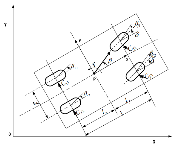
Figure 8: The conventional four-wheel vehicle system
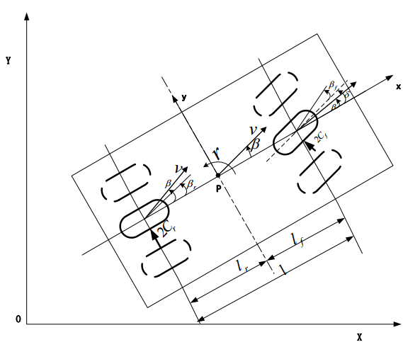
Figure 9: the four-wheeled vehicle reduced to a two-wheeled vehicle for modelling
For the two-wheeled vehicle, there are only two degrees of freedom (2DOF). These are the motion to the front or back, and motion to the left or to the right. These are the motions along the longitudinal axis and motion about the normal or vertical axis of the vehicle. These 2 degrees of freedom are used to set up the vehicle kinematics equation by determining the yawing angular velocity and the sideslip angle in the motion (Han et al., 2017).
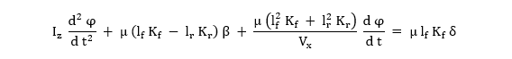
The equation for the sideslip angle is modelled as:
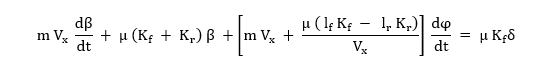
The equation for the yawing angular velocity is modelled as below:
These two equations for the yawing angular velocity and the side-slip angle can be expressed in matrix form where it’s assumed 
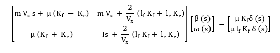
The equations above can be expressed as differential equations. Its expression is shown below:
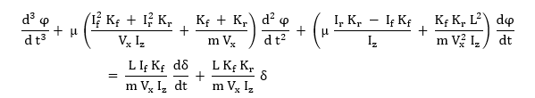
The values on the left-hand side are equated to a0 and a1 while the values on the right-hand side are equated to b0 and b1 as shown below:
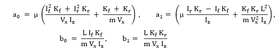
The differential equation can then be simplified to the equation below:
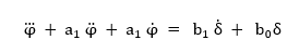
But , therefore, the transfer function is modelled as below:
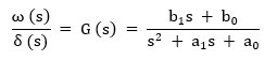
This is a second-order transfer function which can be effectively modelled by a PI controller, the derivative control will be added to increase the system’s stability (Han et al., 2017). Therefore the control system implemented is the PID control.
5.2. Parameters and symbols used in modelling the vehicle:
Table 1: Table showing the symbols used and the values used in modelling
| Sign | Meaning | Value |
| V | Vehicle velocity | ≤ 72 km/h |
| Corner stiffness of the rear tyre | 33000 N/ rad | |
| Corner stiffness of the front tyre | 19000 N/ rad | |
| Distance from the COG to the rear axle | 2.1 m | |
| Distance from the COG to the front axle. | 1.7 m | |
| The Yaw moment of inertia | 2875 kg m^2 | |
| m | The mass of the vehicle | 1370 kg |
| The coefficient of friction between the road and the tyres | 0.7 | |
| Length × Width × Height | The dimensions of the vehicle | 4.096 m × 1.765 m ×1.653 m |
The vehicle velocity of 72 km/h was chosen because it is a speed at which there will be full control of the vehicle to bring it to a stop or to manoeuvre when yawing to avoid collision. 72 km/h is equivalent to 20 m/s. the vehicle modelled is a car, therefore the dimensions in length width and height are chosen to reflect the dimensions of the New Ford EcoSport 2018. The weight of the car is also approximately 1370 kg. The coefficient of friction used is for a dry road surface which is 0.7 according to Jones and Childers (2001).
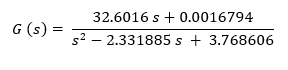
The values constants in the transfer function can be calculated and substituted so that the transfer function of the model can be modelled in MATLAB. The computed values for a0, a1, b0, b1 are shown below:
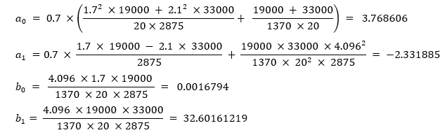
The transfer function for the car after finding the constants is represented as below:
5.3. Modelling and Simulation of the Transfer Function in MATLAB
The above function can be simulated effectively since the transfer function defines a second order system. The software that can be used are either LabVIEW or MATLAB to effectively achieve the control. In this paper, the MATLAB & SIMULINK has been used to come up with the model. Step by step implementation of the model will show how the output signal is affected by different parameters that are adjusted. The control system to be used has to be a PID system because the transfer function is a higher order non-linear system (Magrab and Azarm, 2000). PI control can be used to achieve the control, however, it will not be as stable as the implementation of the PID. The sequence of steps in implementing the control is first coming up with the system without any control so that the output signal can be compared to the input signal. The desired feedback control mechanisms are implemented, the change in the output signal is monitored at every stage of implementing the desired control.
5.3.1. Modelling of the system open loop response without any controller:
The open loop response of the system without any controller is the basic simulation so that the response of the system can be monitored. Modelling the open loop response is done so that it can be compared with the other closed-loop responses of the system when implemented. The open loop response is shown below:
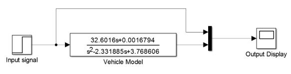
Figure 10: The Vehicle Open Loop System without a controller
In the block diagram above, the input signal represents the driving input to change the steering angle so that a change in direction will be made to avoid collision with any obstacles. In case there is no ability to change lanes, this signal will enable the car to slow down. The vehicle model is all the parameters of the two-wheeled vehicle model brought under one transfer function. It combines the friction of the tyres on the road, the momentum of the car (found by the product of mass, velocity and the yaw moment of inertia), the sideslip and the yawing angular velocity to avoid the collisions. For our modelling, the speed of 20m/s selected. However, when a higher speed is selected, the transfer function is bound to change because the Vx in the equations will be affected (Liu and Chen, 2013).
Before the output display is a multiplexer that is used to combine the input step response and the outputs signal from the plant (vehicle model). This just helps us compare the input step and the output signal in the modelling process. The output display shows the two signals from the step response and the output so that the desired control can be implemented to bring the system to stability. The aim of the modelling is to bring the system to stability n the shortest time, this is because a vehicle moving needs to change lanes or slow down quickly to avoid any collisions. For instance, the vehicle has to have a quick response to avoid oncoming traffic bearing in mind their relative velocity is higher. These changes in the yaw have to be very stable or else the car will roll and cause fatalities.
The input and output signals from the model shown above are displayed below:
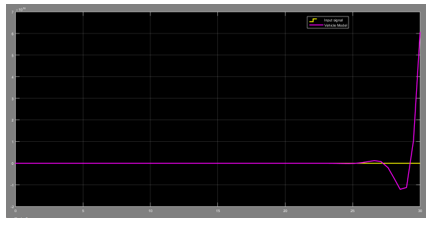
Figure 11: The vehicle input and output signal compared
The figure above shows the response of the system after 30 seconds. The pink line gives the output signal of the system, while the yellow curve shows the input step response. From the representation above, the input and the output response seem to be equal until the 25th second before the output response starts oscillating rapidly and be very unstable. The input step is 7V, by the oscillations after the 25th second is to the tune of > 1×10¹⁶. From the first to the 25th second, the response seems to coincide, but the magnification of the two shows that the error (the difference between input and output) is greater than 20000 V. this difference is large and the system is basically unstable. This means a small change in the steering angle leads to a very large change in the sideslip angle and the yawing angular velocity that could be catastrophic. The magnified signals are shown in figure 12 below:
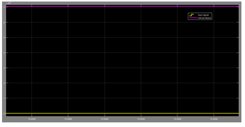
Figure 12: The magnified response at the 10th second
The figure above magnifies the signal response at the 10th second. The input step is then compared to the output step. From the diagram above, the input step is shown to be 7V, but the output signal has a value higher than 7 × 10⁶ volts. The error difference is too high, this ought to be corrected through the implementation of a feedback controller. The before implementing any control mechanism, it is interesting to check the signal response with the feedback as shown below:
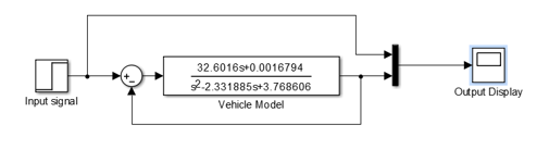
Figure 13: Closed loop system with the feedback
In the diagram above, the output is fed back to the system. At the comparator section, the feedback is subtracted from the input so that the error signal is fed back to the vehicle model. The signal corrects the difference between the input and the output of the system (Padula and Visioli, 2013). The output of the system is shown below:
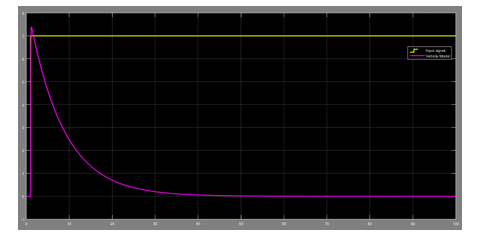
Figure 14: Signal response with feedback in the loop
In the closed loop response above, the systems error is reduced. In figure 12, the open loop response had a difference of more than 7 × 10¹⁶ V between the input and the output signal. However, when the error reduced, the difference is reduced to about 7 V. in figure 14 above, the output signal rises as the step with an overshoot of approximately 0.4V, it then smoothly decreases to 0 V after 50 seconds. When the signal was magnified, the output response showed small oscillations in its curve. The magnified curve is shown below:
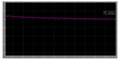
Figure 15: Magnifying the output response curve of the vehicle
The signal was magnified between 50 and 75 seconds to show the oscillations in the curve, rather than it being under no magnification showing a smooth curve. These perturbations will present a vibration in the vehicle’s structure as it yaws to avoid collision (Dorfman, 2013). The perturbations out to be removed to have a smooth curve.
5.3.2. Implementing the PID controller for the Vehicle System:
The function of the PID control is to reduce the error of the system to zero, increasing the response speed and increase the stability of the system to reduce the perturbations that could lead to vibrations in the structure of the vehicle. The perturbations will not have an adverse effect on the stability of the vehicle, but the clutter will be uncomfortable for the passengers in the vehicle. To begin the response modelling, a Kp gain of 1, Ki gain of 1 and Kd of 0.2 is chosen arbitrarily for modelling.
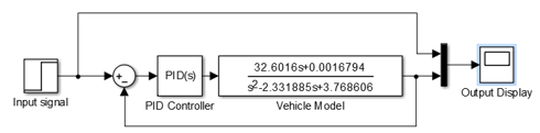
Figure 16: Closed loop system with PID control; Kp = 1, Ki = 1, Kd = 0.2
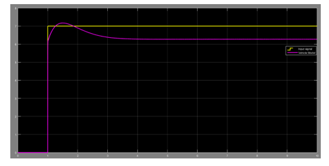
Figure 17: the output response of the closed-loop system
The closed-loop system with the selected gains in the controller reduces the error between the input step and the output of the system. The overshoot and the settling time is reduced (Dorfman, 2013). The system is stabilised after approximately 4.5 seconds. The overshoot, in this case, does not have a sharp peak, but it is a smooth curve at the peak. This shows a smooth system as it is damped to find its rest point.
For a vehicle moving at 20m/s, finding stability after 4.5 seconds is a lot of time. This is because the distance travelled will be approximately 90 metres (D = S×T = 20 m/s × 4.5 seconds = 90 metres). The settling time for the output signal has to be reduced to increase the accuracy and stability of the system (Mikleš and Fikar, 2007). This is achieved by changing the values of the gain in the controller to achieve the desired control output. The control achieved by the PID tuning tool in the Simulink library.
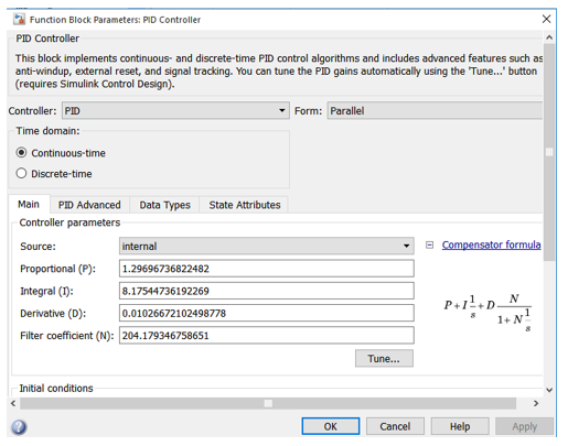
Figure 18: the tuned values of Kp, Ki and Kd
In the figure above, the tuned Kp, Ki and Kd responses are 1.297, 8.175 and 0.0103 respectively. The output response for the tuned signal is shown in the figure below:
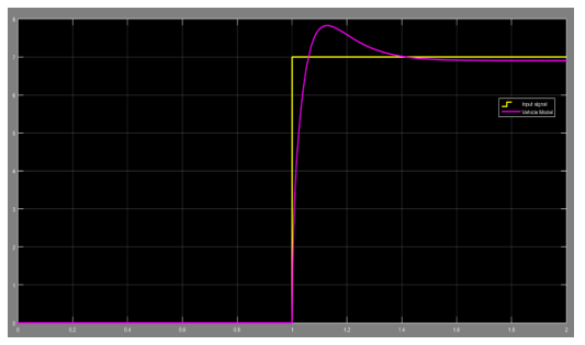
Figure 19: Adjusted Kp, Ki and Kd to achieve a smooth response fast response and shorter settling time
In the figure above, the response time is reduced such that the settling time for the output curve is approximately 1.7 seconds. This duration is shorter than the output response in figure 17 where the output settled after 4.5 seconds. For a vehicle system that has to avoid both dynamic loads and static loads, a settling time of 1.7 seconds means that the vehicle has a stable manoeuvre within 1.7 seconds. The inertial resistance to the change in slip angle and the yawing angular velocity is within the desired limits and the output is stable. The MATLAB model developed and simulated, therefore, ensures the autonomous car efficiently changes the lanes and avoids collisions (Han et al., 2017).
Chapter 6: FINDINGS AND DISCUSSION
Chapter 4 and Chapter 5 discussed the modelling of the system in MATLAB & SIMULINK. In chapter 4, the modelling focused on the code to be used for the sensors to avoid the collision. In this code, robots were used to imitate vehicles, the robots were to move from one selected point to another while avoiding collision with other objects along its path to the generation. The code mimics the operation of the code in the controller of the car to avoid collision with other dynamic and static objects along the path of motion. In chapter 5, the vehicle’s parameters were considered and a transfer function used to model the system. This was meant to observe the response of the car to the steering signals after considering its speed, momentum, traction of the tyres on the road and the vehicle’s stability (Tedesco, Raimondo and Casavola, 2013). The vehicle chosen for modelling was the New Ford EcoSport 2018. Any car would have been chosen since the system is modelled depending on the parameters of the car, there were no particular qualification criteria for the Ford EcoSport 2018. The vehicle parameters were available from the manufacturer details, this increases the credibility of the modelling criteria.
In the open loop response, the error in the output of the car and the input step response was very high. The transfer function of the car is a second order system that has a nonlinear response to the input. This was the reason for the fluctuation of the curve to high levels after approximately 30 seconds. In conventional control, this means that the car will respond well to the steering but will be unstable moments after the car changes the slip angle (Pawelec, 2008). Such an unstable car is bound to cause road accidents and fatalities. When a closer magnification was inspected between the input step and the output signal. It was found that the output signal had much higher output than the step signal. This implies that a small change in the input leads to an excessive change in the output. For a steering system, a small change in the steering angle will lead to a large change in the slip angle in the tyres. Rather than taking a smooth yawing angular velocity to avoid collision, the vehicle will have a large slip angle which may lead to rolling off the road.
To reduce the error between the input and the output, a feedback mechanism was implemented together with a three-term control. The proportional control was used to increase the response speed and the accuracy of the system. The use of the integral control improved the accuracy of the system further. The use of these reduced the error in the system between the input step and the output signal (Driels, 2010). It was observed that the output signal had a reduced margin from the step signal. However, there were small perturbations in the output signal. These perturbations do not always affect the overall control of the system but always present clutters and vibrations that are uncomfortable to the passengers. These vibrations also wear down some of the car’s components like the window frames. To achieve higher stability and a smooth output curve, the derivative controller has to be introduced to ensure the output curve is smoothed (Liu and Chen, 2013). The introduced derivative controller increased the response speed to make the output signal have a shorter rising and settling time. In addition, the stability was improved because the controller reduced the oscillations (perturbations) in the output signal. To increase the efficiency of the output signal, the PID tuning tool was used to tune the system to pinpoint accuracy.
The use of the controllers works well with the sensors. The sensors get information from the traffic around it describing the motion of the objects in the trajectory of the vehicle. These sensors work on the Doppler Effect to determine the loads in its direction. The variation in the Doppler frequency will determine whether the obstacles are static, dynamic, the distance to the obstacle and the space available for the autonomous vehicle to make the manoeuvre (Srinath and Ramakanth, 2009). The information from the sensors is fed to the controllers to determine the yawing angular velocity and the slip angle of the tyres. The effective angles yaw angles to be taken and the speed of the vehicle is then fed to the car system to swerve and avoid the collision. The input signal, therefore, comes from the car sensors which are fed to the yawing system to make a steady, stable and quick collision avoidance manoeuvre (Pawelec, 2008). In case the system is not able to change lanes since other cars are in the lanes, the control system is then activated to slow down the car to a stop if the obstacle is static or to the desired speed is the obstacle is dynamic. Through this, collision is avoided.
In the modelling above, the assumptions made were that the four-wheeled car was reduced to a two-wheeled system having only one from the tyre and one rear tyre. Generally, this may not always be the case for four-wheel drive vehicles since all the tyres will have almost the same traction on the road surface to increase the stability of the vehicle. This was done to make the transfer function easier to model. In the model, the car was assumed to have a speed of 72 km/h, this speed was arbitrarily taken for modelling. It gives a round figure that can perfectly model the car when converted to m/s. A small change to the velocity of the car will not have a large change in the transfer function, but a larger change in the transfer function will need a remodelling of the transfer function to match the speed requirements. In actual systems, the car needs a real-time update of the speed fed to the controller so that the control function can be adjusted according to the changes in the vehicle speed (Pawelec, 2008).
The collision avoidance system above was meant for a car in motion in traffic. However, autonomous cars also need the system for car parking in Brisbane International airport. In this case, only the velocity of the vehicle is reduced to the desired speed in parking. The obstacles while parking is always static. The system is extended to ensure that there is no collision to the static objects in the parking trajectory of the vehicle (Tedesco, Raimondo and Casavola, 2013).
The collision avoidance system was implemented successfully and the desired control achieved in the simulation. The sensor system worked well while the control system showed the response of the controller tuning on the output stability of the system. In case alternative effects to the output signal are to be achieved, the values of the gains for Kd, Ki and Kp are just adjusted.
Benefits of the System:
As discussed in the literature review, the number of collisions on the roads per year is very high. The fatalities cause pain and have economic impacts when the skilled workforce are either rendered dependants or lose their lives. The economy of the country suffers since the insurance costs are increased, the treatment costs and sometimes the people are rendered incapable of performing their skilled duties. Implementing the collision avoidance systems for the autonomous vehicles will decrease the number of accidents. The vehicles and communicate to each other and take the necessary actions before the collision. In the airline industry, collision accidents have been avoided by the use of Traffic Collision Avoidance System (TCAS), this reduced the frequency of aircraft accidents since the autopilot controls the aircraft to avoid hitting obstacles (Kharchenko, Barabanov and Grekhov, 2013). If the system is adapted for automobiles, the number of accidents will be reduced too.
Reduced accidents will lower the cost to the state in repairing the damaged roads and structures. Vehicles that lose control collide with signposts, guard rails, buildings and other obstacles along the way. Most of there are always owned by the state and need thorough repair and maintenance after they have been damaged. A collision avoidance system will reduce the cost to the state. The insurance costs will also reduce since the companies will have to pay for compensations less often. The sector will be ranked a lower risk sector which reduces the premiums to be paid in insurance. The cost to the car owners is also reduced in making the repairs to the vehicles and medication if they are injured in the accidents (Mahmassani, 2005). Money saved in avoiding these accidents and fatalities can be channelled to other activities that will provide more utility and financial benefit to the individuals and all other sectors involved.
The use of the collision avoidance systems together with global positioning system and traffic flow information from the nation traffic databases can reduce the traffic jams on the roads. The system receives information from the GPS systems and selects roads that are less crowded to use less time to reach the destinations. This saves on the cost of fuel and the time that could be wasted in the traffic jams. It, in the end, saves the cost to the state because the people will be more productive from the time-saving. It also increases convenience for the passengers. In a report by BBC in February 2018, the number of hours spent in traffic per individual per year is shown in figure 20 below. London ranks the highest with approximately 75 hours lost per year (BBC, 2018). Through the use of the collision avoidance systems in conjunction with real-time traffic databases and GPS systems, the hours wasted on the roads can be greatly minimized to spur economic growth.
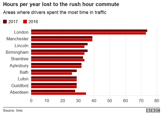
Figure 20: Number of hours spent in traffic jams in major cities in the UK per person per year
Business systems manage the world. Saving time and cost ensures more value is attained for the work done and the contracts. The improvised systems will allow the different stakeholders to save time and money for other stakes.
Chapter 7: POTENTIAL CLIENTS
The collision avoidance system has large-scale application in the autonomous vehicles in the automobile industry. The vehicle manufactures can take on this opportunity to test it and implement it in their vehicles. Sample car manufacturers that may use the system are Ford, Toyota, Audi and all other manufacturers. Apart from yawing to the left or to the right to change lanes and avoid collision, the system can be implemented in lorries and trucks to avoid collision with high obstacles like power lines, footbridges, tree branches and other systems that restrict the height of passing vehicles. In the automobile industry, the other function is using the system in parking system. This avoids collision with other vehicles in the parking slots (Pawelec, 2008). For taxi operators like Uber, the use of such systems in their autonomous vehicles increases efficiency and lowers the cost of operation. When the system is implemented in the taxi and linked with the GPS, it can learn of the traffic flow on the road and ensure its speed and manoeuvres avoid collision through the entire journey from the start to the destination. The company gets customer satisfaction and better control of its fleet.
The collision avoidance system is also used in the aircraft industry. It is used in the aircraft is called the Traffic Collision Avoidance System (TCAS). When modelling it to use in the aircraft, rather than using the coefficient of friction of the road, the aerodynamic drag is used and integrated to be applied to the whole aircraft’s body. The TCAS is used in flight, while on the ground, the aircraft can use this system to avoid collision of its wings or landing gear with the objects, buildings or other aircraft on the ground. The TCAS is more expensive and particularly adapted for flight in large aircraft, it is switched off while the aircraft is on the ground. The pilots depend on the control tower for information, aircraft marshalling, and tow systems to avoid collision (Kharchenko, Barabanov and Grekhov, 2013). The implementation of the collision avoidance systems on aircraft will provide greater ease for the aircraft on the ground. This is similar to the ships and other marine vessels. Collision can be avoided en-route or in the parking harbours if the system is implemented.
The system can also be used in defence applications for the Unmanned Aerial Vehicles and missiles. For the unmanned aerial vehicles, the system is used to avoid obstacles in the trajectory that are either unprecedented or well planned for. For instance, when a toy drone is flying, it can avoid collision with trees, walls, cloth lines and other obstacles on its way. Similarly, defence drones are designed not to be detected on radar, while flying through the air, the drone can avoid collision with unsuspecting aircraft while on its mission. Missiles also have to have proper collision avoidance systems unless they reach the required target. A missile should not any hit flying objects on its path unless it is the target (Srinath and Ramakanth, 2009). Therefore, defence systems need to use the system for security and achieving the required defence goals.
Blind men need white sticks as they walk around. The white sticks may not efficient in places with high population and busy activity. The companies manufacturing utilities for blind men can make either goggles or other devices that implement the collision avoidance mechanism (Anwar, 2017). They collision avoidance spectacles and other light devices will increase the mobility of the blind people as they navigate through the cities, homes, streets and other places without colliding with objects and other dynamic obstacles. The collision avoidance ‘spectacles’ for the blind have to be more defined because pavements for pedestrians are not like roads. Roads are flat and often have a common direction of travel, for pedestrians, the modelling is more chaotic since the dynamic obstacles (fellow pedestrians) move in different direction at any given one time. Having the collision avoidance spectacles working together with the white sticks can help navigate easily. Other than collision avoidance spectacles, the manufacturer may incorporate the sensors and collision avoidance control in the white sticks (Anwar, 2017). This provides more utility and flexibility even when the terrain is rugged.
In stores and warehouses, collision avoidance is also needed to prevent the damage of goods stacked and stored. Storage space is often scrambled for in the warehouse. The forklifts are left with just enough space to allow them to move from one location to another. When the forklifts are made fitted with the collision avoidance systems, they become more efficient and can operate at a higher speed. In case a forklift collides on its trajectory, the goods it carries may fall of the static obstacle may contain priceless stock (Tedesco, Raimondo and Casavola, 2013). Therefore, the use of the designed system will prevent any damages that would result from the collision of the vehicles. The warehousing costs are thus reduced since the storage process is simplified.
The collision avoidance system has many applications in the industry today. When the advanced system is developed, it will get a variety of other applications that will define business and technology for the future. The benefits of engineering systems are that once a technology is invented, there is an exponential increase in its application in all the engineering fields. The innovators, scientists and designers often use the concepts borrowed from different fields to implement systems that satisfy a specific need in society.
Chapter 8: CONCLUSION AND RECOMMENDATION
The challenge an autonomous vehicle is that it needs to overcome instability and to avoid collision with any static or dynamic obstacle along its path of motion. This signifies that autonomous vehicles should possess the capabilities of performing emergency manoeuvres in case it detects any obstacle. To avoid any static or dynamic obstacle on the path of autonomous vehicle it has to either decelerate to complete stop on the same lane or to manoeuvre to the neighbouring lane based on the traffic flow of that lane (Brandt et al, 2005). This project focused on designing and simulating collision avoidance system for an autonomous vehicle, not only to avoid collision and maintain the stability of the vehicle but also to maintain traffic flow.
The listed objectives of the study were understanding the concept of autonomous vehicles and the technologies associated with. This was successfully done, the autonomous vehicles were described as vehicles without manned control and they use the GPS systems to navigate from point to point after the trajectory is selected. The technologies available for collision avoidance were also studies and limitations improved in the model developed. The other objective was to develop a dynamic model for the autonomous vehicle and design a trajectory to be followed by the vehicle. This was done in the MATLAB code for the trajectory to be followed. The PID control was then designed to ensure that the controller of the system achieves the stability in manoeuvring within the desired time constraints for stability and effective control (Padula and Visioli, 2013). The objectives were successfully achieved in the project.
The benefits of the system discussed extensively. One of the benefits was to reduce the frequency of road accidents, the impact was reducing the cost to the individuals, to the state and the insurance companies. Avoiding the financial losses redirects the funds to projects and other activities that lead to economic development. Increasing the safety of the passengers makes them have the vital energy to work for economic progress. The collision avoidance system also reduces the lost time in traffic jams. This ensures the people are able to reach their destinations in time and engage in the activities. This increases convenience, fuel saving and saves on key resources. Developing the system to advanced use is vital for economic progress as well as the individual progress of all the stakeholders who use the system. The benefits can then be extended to other engineering systems for wider variety applications for safety.
The project, however, focused on the vehicle dynamics and sensors only, it never integrated all the vehicle systems to achieve the perfect control (Han et al., 2017). For instance, when one has to avoid collision for vehicles moving in the same path, it yaws to the left or to the right then increases its speed to overtake the vehicle before it switches back to its original lane. The modelling done has not factored the other part that overtakes the vehicle and switches back to its lane after overtaking. In addition, the model has not fully implemented the system to slow down the vehicle from a higher velocity to a lower velocity in case overtaking is not possible. The modelling only assumed that in case there is an obstacle ahead, then the vehicle will perform a yaw. Further analysis and research ought to be done in subsequent projects to include the module for overtaking and returning back to the lane and also for slowing done in case there is no chance of overtaking the obstacle.
The system concept also has a wide variety of applications in the different engineering industries. It can be implemented in forklift design, aircraft parking and towing systems, aiding the blind navigate the streets and pavements and also in car parking systems. The implementation of these systems in the individual sectors is not straight-forward, rather it needs modelling to match the specifications of their use. The research into these industries and systems can be conducted so that effective solutions can be improved to create utility to the system.
The challenge in the project was coming up with the parameters that define the vehicle so that its control system could be designed. For instance the moments of inertia, the coefficients of friction between the vehicle tyres and the roads, the cornering stiffness of the front and rear tyres. All these vary in different vehicle designs. A more specific approach can be implemented. A model car can be used and its parameters used to design a bespoke control system rather than using dimensions of just any vehicle. Narrowing down the design to a specific vehicle makes it easier to get the vehicle parameters for assessment of its control system (Khairnar, Phalle and Mantha, 2015). If the approach remains for any vehicle design, it will not be possible to come up with feasible solutions because manufacturers have different designs for their individual vehicles. They have individual approaches to the design and manufacture of their automobiles.
Apart from the challenges in coming up with the perfect model for the car from the mathematical modelling, all the other systems and work was achieved well in line with the project’s requirements. I would recommend further control engineering classes for greater efficiency in modelling the systems from the first principles in control system design. The mass balance systems, electrical and electronic systems and examples in real multi-body complex system analysis and modelling will provide a firm foundation for the students in the faculty and in the engineering applications in the work environment. The subsequent projects should focus on integrating the communication system of the autonomous vehicle with all the vehicle systems and communication with the GPS satellites for navigation.